← 18. The security agreement · Contents
19. A DIY reader
A hardware build log, written for a complete beginner. It turns a Raspberry Pi Pico clone and a handful of cheap modules into a badge and PIN reader on a single breadboard. It is the reader half of a node in 16. The lab suitcase. Nothing here changes what a controller does.
A beginner's page
I know very little about electronics, and I had not touched a soldering iron in more than 15 years. This whole page is written from a beginner's point of view, by someone doing it for fun. The result is not professional work. It is what any beginner can reach by taking a bit of time, and every mistake along the way is listed at the end.
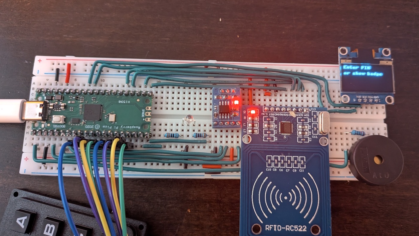
The reader reads a badge or a PIN, lights an LED, beeps and shows a message. In wardn, it will never decide on its own: it sends what it read to the controller over OSDP, and the controller answers. The first parts build a reader that decides locally, so that each piece can be tested. The last parts move that decision to the controller, one OSDP command at a time.
flowchart LR
    B["Badge"] -- radio --> R["RC522"]
    K["Keypad"] --> P["Pico"]
    R -- SPI --> P
    P -- I2C --> S["OLED screen"]
    P --> L["LED + buzzer"]
    P -- "3.3 V pulse" --> D["Door"]
    P -- UART --> M["MAX3485"]
    M -- "RS-485 (A, B, GND)" --> C["Controller"]
How to read this page. Each part is short and ends with a test. Do not move on until the test passes. The prototype runs MicroPython: it is easy to poke at, and it is not meant for production.
Contents
- What you need
- All the code
- Meet the Pico
- Solder the headers
- The bicolor LED
- The RC522 badge reader
- The keypad
- The buzzer
- The OLED screen
- Everything on one breadboard
- The full program
- Open the door
- The bus: plain text both ways
- Talking OSDP
- What comes next
- What went wrong, and the fix
- Glossary
What you need
The shopping list below is exactly what this build used, with the price paid in September 2026, in euros, shipping excluded. Many items come in packs: one pack is enough for several readers.
The reader: about 31 €, plus a keypad and a buzzer.
| Part | Price | Notes |
|---|---|---|
| Raspberry Pi Pico | 3.61 € | The listing offers several variants. A USB-C RP2040 clone arrived, and it works the same |
| MB-102 breadboard, 830 points | 3.83 € | 63 rows, printed 0 to 62 |
| RC522 RFID module | 2.01 € | 13.56 MHz, comes with a card and a key fob |
| 0.96" OLED, SSD1306, I2C | 4.22 € | 128×64, 4 pins |
| MAX3485 module | 1.53 € | 3.3 V RS-485 transceiver, 120 Ω termination on board |
| Bicolor LEDs, red and green, 3 mm | 3.14 € | Pack of 100, common cathode |
| Resistor kit, 1/4 W | 2.82 € | 30 values. You need 330 Ω and 220 Ω |
| Male header pins, 2.54 mm | 3.36 € | 10 strips of 40 |
| 22 AWG solid wire | 1.84 € | For the flat wires. Red, black and green |
| Dupont wires | 4.29 € | Male-male, for the keypad cable |
| 4×4 matrix keypad | — | Came from an Arduino starter kit. Search for "4x4 matrix keypad", with an 8-pin connector |
| Passive piezo buzzer, Murata PKM22EPP-40 | — | Came from an old Arduino starter kit. Any passive 22 mm piezo works |
Tools: about 39 €, bought once.
| Tool | Price | Notes |
|---|---|---|
| Soldering iron FNIRSI HS-01 | 25.59 € | Temperature-controlled. Needs a 65 W USB-C charger |
| Rosin-core solder, 0.8 mm | 2.59 € | 60/40 |
| Brass tip cleaner | 2.39 € | A damp kitchen sponge also works |
| Multimeter ANENG SZ304 | 8.63 € | Continuity, diode and Ω modes are all used here |
Also: a wire stripper and cardboard to protect the table.
For the OSDP parts and beyond
| Item | Price | Notes |
|---|---|---|
| Waveshare USB to RS-485 adapter | 16.49 € | Lets a laptop play the controller over the bus. CH343 chip: macOS needs no driver |
| 3M Dual Lock | 9.95 € | To mount the keypad on a front panel |
| Raspberry Pi 4 | — | The real controller, running wardn-edge |
All the code
Every file that goes on the Pico, ready to download. Copy the three libraries once, then one program per part.
Libraries, saved on the Pico under the same name:
| File | What it is |
|---|---|
mfrc522.py | RC522 driver, with two fixes (part 4) |
ssd1306.py | Screen driver, unchanged, from micropython-lib |
osdp.py | OSDP frames. Also used on the Mac by controller.py (part 12) |
On the Mac: controller.py plays the controller over the RS-485 adapter (part 12).
One program per part. Open it in Thonny and press Run. Save it as main.py on the Pico to have it start on its own at power-up.
| Part | Program |
|---|---|
| 1 | 01-blink.py |
| 3 | 03-led.py |
| 4 | 04-badge.py |
| 5 | 05-keypad.py |
| 6 | 06-buzzer.py |
| 7 | 07-screen-scan.py, 07-screen.py |
| 9 | 09-full-program.py |
| 10 | 10-door.py |
| 11 | 11-hello.py, 11-receive.py |
| 12 | 12-1-poll-ack.py, 12-2-id-cap.py, 12-3-badge-keys.py, 12-4-controller-decides.py |
The pins are those of the final breadboard (part 8).
1. Meet the Pico
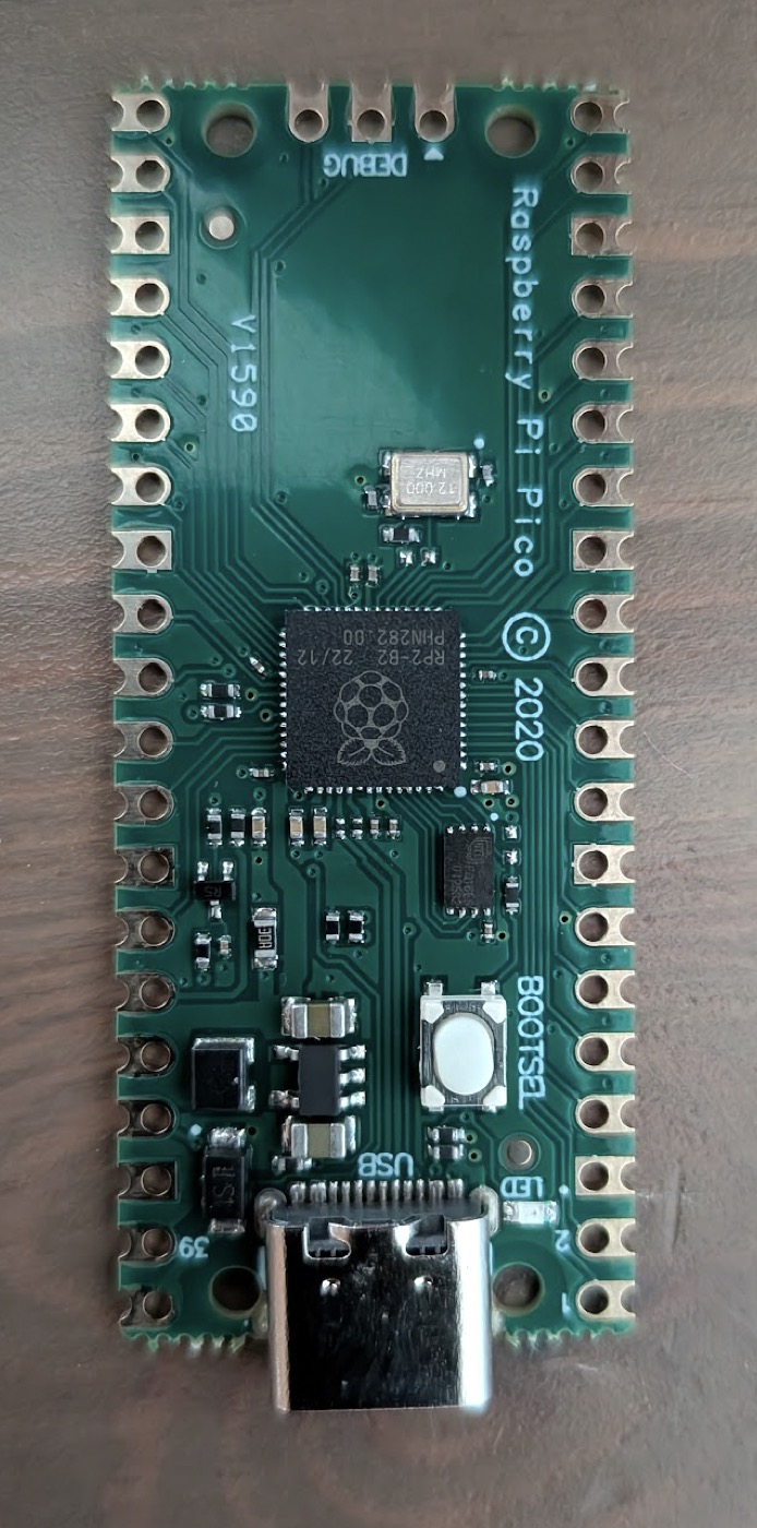
A microcontroller runs one program, with no operating system. The Pico's chip, the RP2040, is marked RP2-B2 on clones.
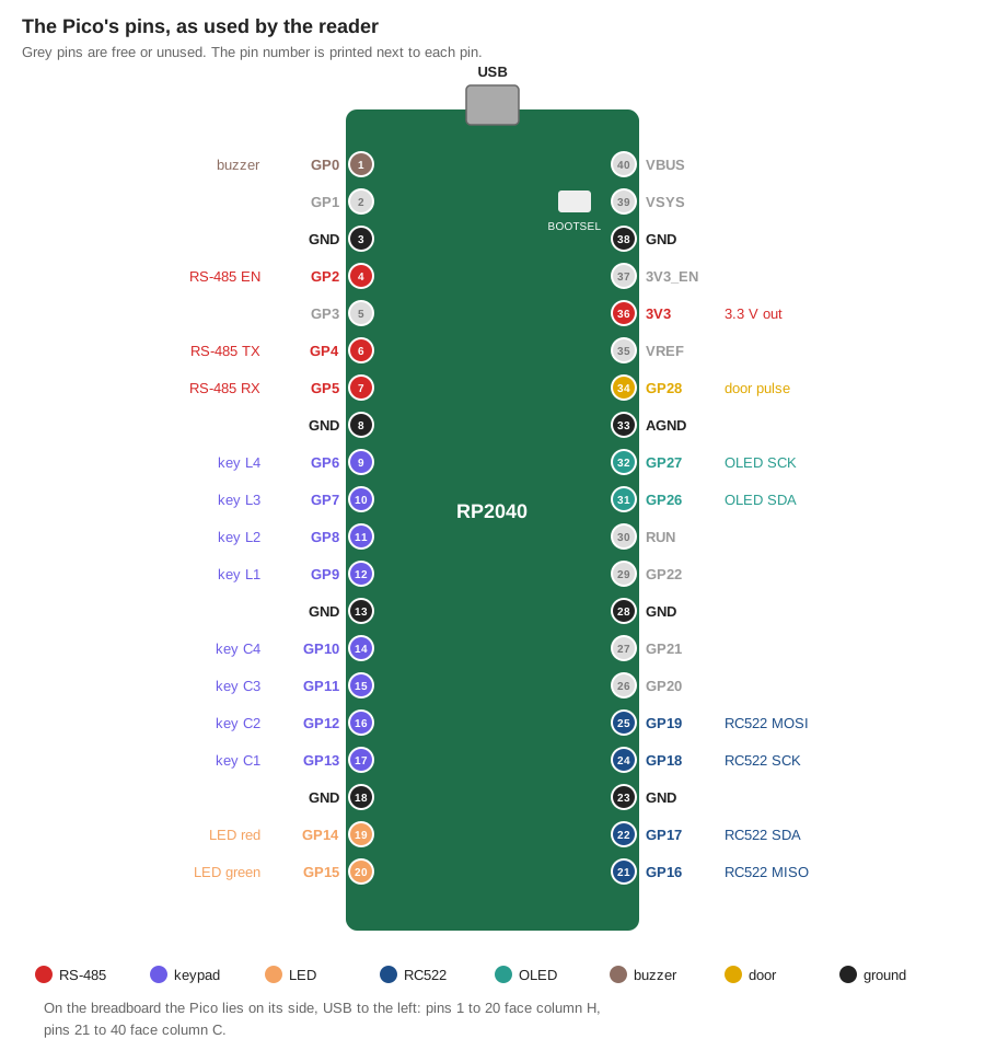
Each of its 40 pins has a number (printed on the board) and a role. Most are GPIOs, GP0 to GP28: pins the program can switch or read. Here is what the finished reader does with each one.
Flash MicroPython (5 min)
- Hold the BOOTSEL button and plug the USB cable in. A drive called
RPI-RP2appears. - Download the latest
RPI_PICOfirmware (.uf2) from https://micropython.org/download/. - Drag the
.uf2onto the drive. The drive disappears: that is expected.
Talk to it (10 min)
- Install Thonny.
- Bottom right, pick the interpreter MicroPython (Raspberry Pi Pico).
- In the Shell, type
print("hello"). The Pico answers.
Test: blink the onboard LED. Save this as main.py on the Pico. It runs at every power-up.
from machine import Pin
import time

led = Pin(25, Pin.OUT)
while True:
    led.toggle()
    time.sleep(0.5)
No RESET button
To get back to BOOTSEL mode, unplug, hold BOOTSEL, plug back in.
2. Solder the headers
The Pico comes without pins. Solder two rows of 20 header pins so it can sit in a breadboard.
Use the breadboard as a jig (5 min)
- Push two 20-pin headers into the breadboard, long side down, 7 holes apart (columns
CandH). - Lay the Pico on top, pins through its holes.
The breadboard keeps the pins straight while you solder.
Solder (45 min)
- Set the iron to about 330 °C and tin the tip.
- Touch the tip to the pin and the copper pad at the same time, for 1 to 2 seconds.
- Feed solder on the other side of the pin, not on the iron. It flows into the hole.
- Remove the solder, then the iron.
- Do one corner pin per side first, check the board is flat, then do the rest.
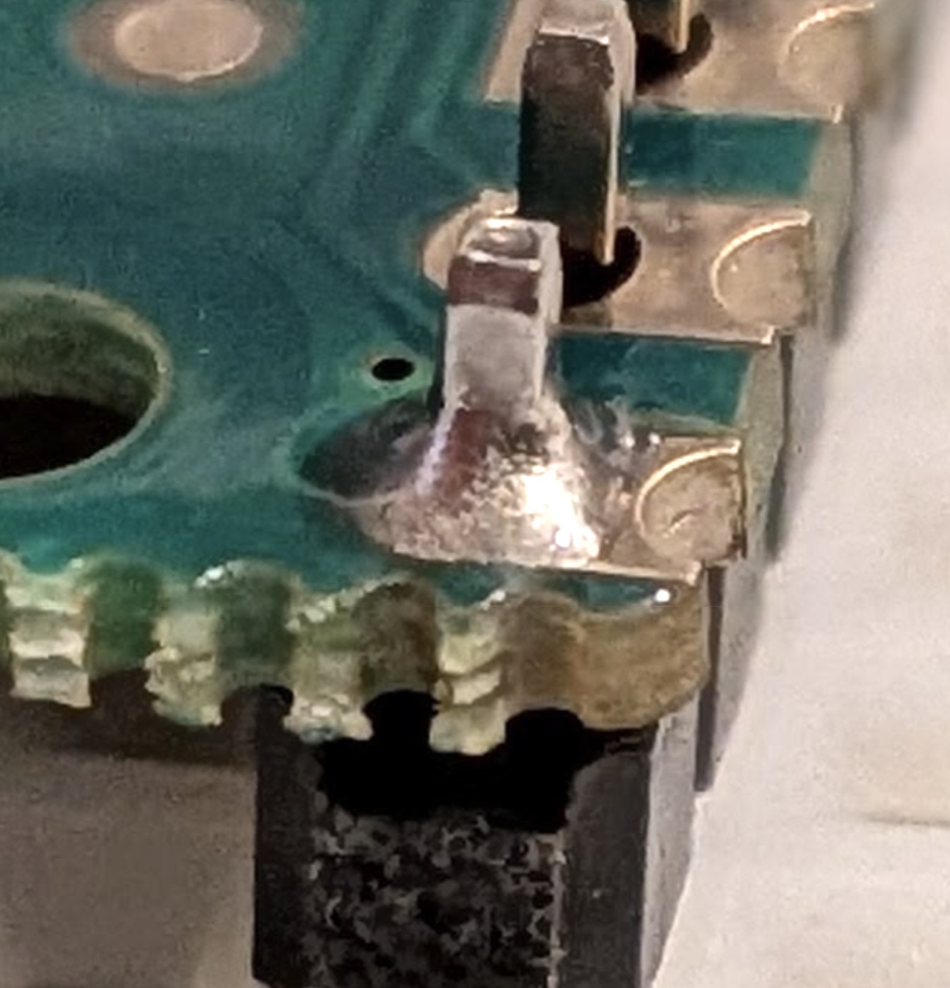
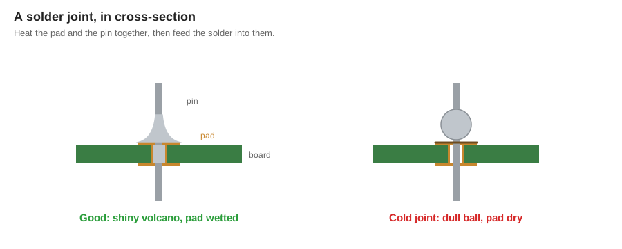
A good joint is shiny and shaped like a small volcano. A dull ball sitting on the pin is a cold joint: reheat it.
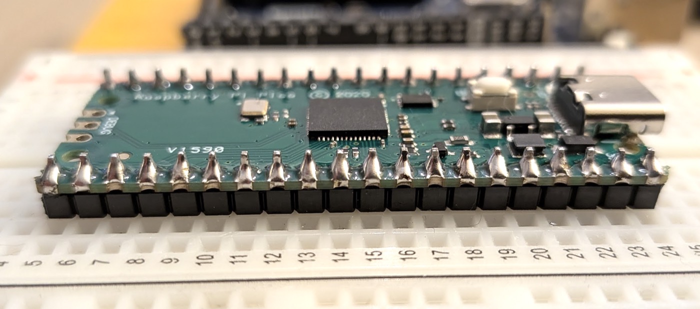
Test: no bridges (10 min). Multimeter in continuity mode ·))). Probe each pair of neighbouring pins, counting from the USB end. No beep between neighbours, except between two GND pins. Then plug the Pico in: the LED still blinks.
Crooked pins in a photo
Pins often look crooked in a photo because of perspective. The real test is whether the Pico drops into the breadboard without forcing.
3. The bicolor LED
An LED only lets current through one way, and it must never be wired alone: without a resistor, the current is only limited by the chip, and something burns.
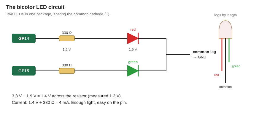
Ohm's law. The Pico outputs 3.3 V. The LED drops about 1.9 V. The resistor takes the rest:
I = (3.3 V − 1.9 V) / 330 Ω ≈ 4 mA
4 mA is bright enough, and easy on a Pico pin.
Find the legs. The longest leg is the common cathode (−). The medium one is red, the shortest green. To check: multimeter in diode mode, black probe on the common leg, red probe on another leg. That colour lights up faintly.
Wire it (15 min)
| Pico pin | Through | LED leg |
|---|---|---|
GP14 | 330 Ω | red |
GP15 | 330 Ω | green |
GND | — | common |
Test. In the Shell:
from machine import Pin
red = Pin(14, Pin.OUT)
green = Pin(15, Pin.OUT)
red.value(1)
Red lights up. green.value(1) adds green: both together make a (very red) orange. You can measure it: about 1.9 V across the LED, 1.2 V across the resistor.
4. The RC522 badge reader
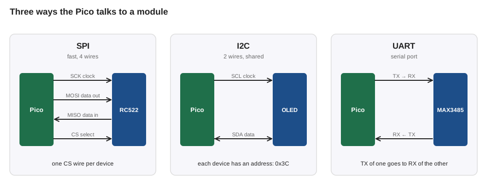
The RC522 powers a badge by radio and reads its UID, a 4-byte serial number. It talks to the Pico over SPI: a clock, a wire each way, and a chip-select. The screen will use I2C, and the RS-485 module a UART:
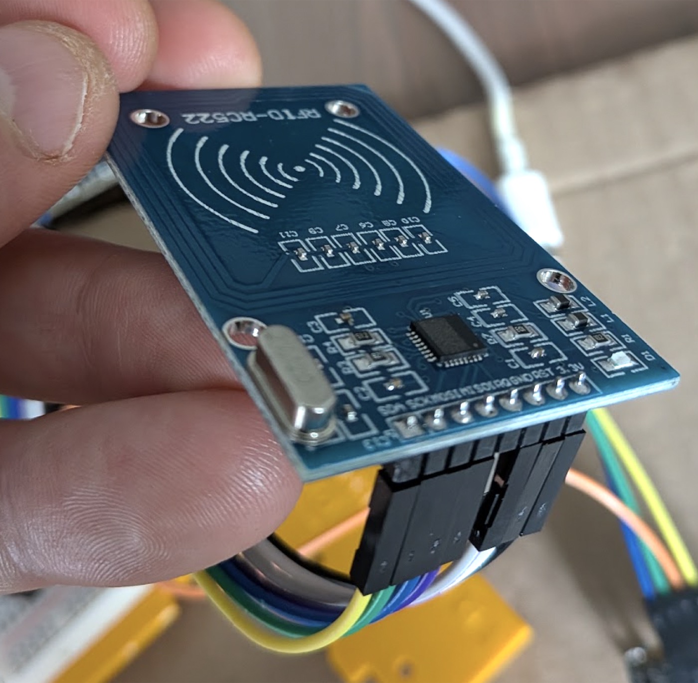
Solder the header (15 min). Pins go through from the component side, long end down, soldered on the back. Tape holds the header square while you do the first pin.
Wiring
| RC522 | Pico |
|---|---|
SDA (chip select) | GP17 |
SCK | GP18 |
MOSI | GP19 |
MISO | GP16 |
IRQ | not connected |
GND | GND |
RST | 3.3V (or GP20) |
3.3V | 3V3 |
3.3 V only
The RC522 is a 3.3 V part. Never feed it 5 V.
Install the driver (5 min)
The driver comes from danjperron/micropython-mfrc522 (MIT licence). The original has two bugs, so use the fixed copy:
- Download
mfrc522.py. - In Thonny, File → Open → This computer, open it, then Save as… → Raspberry Pi Pico, name it
mfrc522.py.
The two fixes, four lines in all, are described at the top of the file:
- One byte, not two. The driver built each byte with
b'%c' % value. On MicroPython 1.29 that turns any byte from0x80up into two bytes, and the RC522 receives garbage. It now usesbytes([value]). - A wait loop that stops. The loop that waits for the RC522 used
~, a bitwise not, as a logical not. It ignored the chip's timer and spun 2000 register reads whenever no badge was present, blocking the Pico for a long moment. It now stops on the timer.
Test: read a badge.
from mfrc522 import MFRC522
import time

reader = MFRC522(spi_id=0, sck=18, mosi=19, miso=16, cs=17, rst=20)
previous = []
misses = 0
while True:
    reader.init()
    status, _ = reader.request(reader.REQIDL)
    if status == reader.OK:
        status, uid = reader.SelectTagSN()
    if status == reader.OK:
        misses = 0
        if uid != previous:
            print("Badge:", reader.tohexstring(uid))
            previous = uid
    else:
        misses += 1
        if misses > 10:
            previous = []
    time.sleep_ms(50)
Hold a badge above the antenna. Its UID prints once, for example [0x6B, 0xAD, 0x30, 0x8E]. The misses counter matters: the RC522 misses some reads even with the badge in place, so a badge is only forgotten after several misses in a row.
5. The keypad
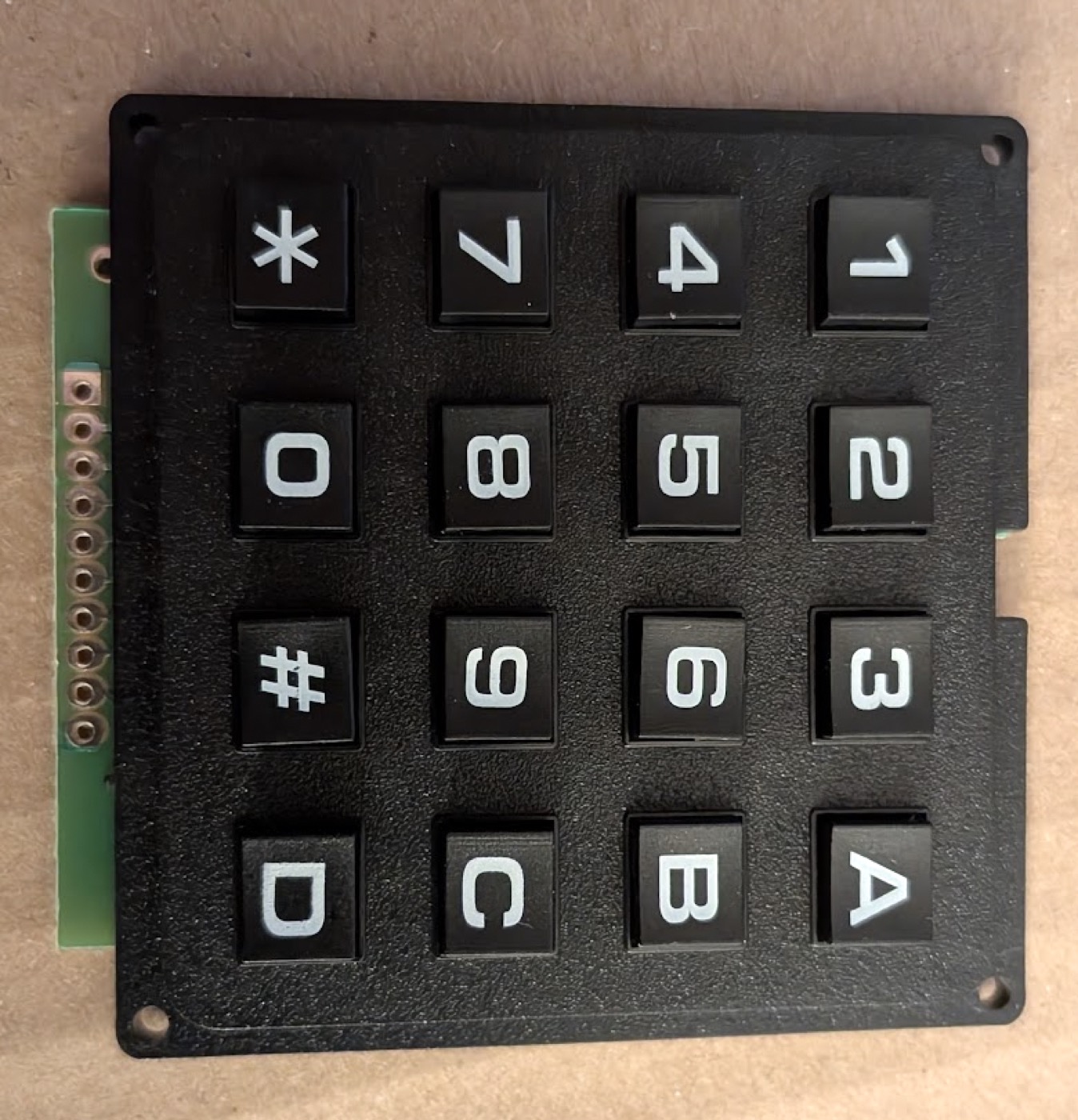
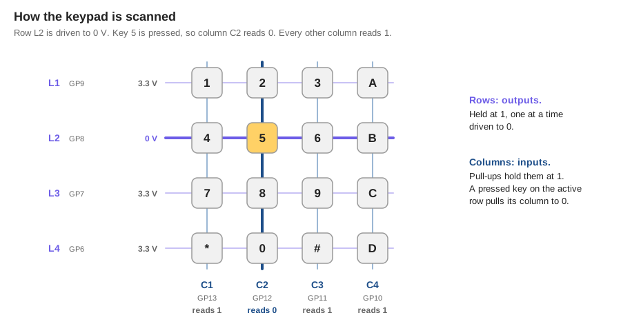
16 keys, but only 8 wires: the keys sit at the crossings of 4 rows and 4 columns. Pressing a key connects its row to its column.
Solder it (20 min). This keypad is single-sided: there is no copper on the back, so the pins are soldered on the key side.
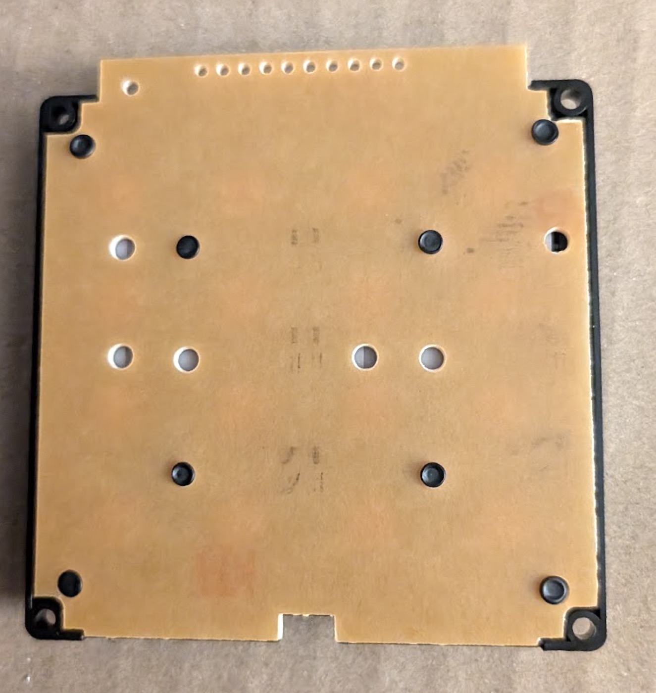
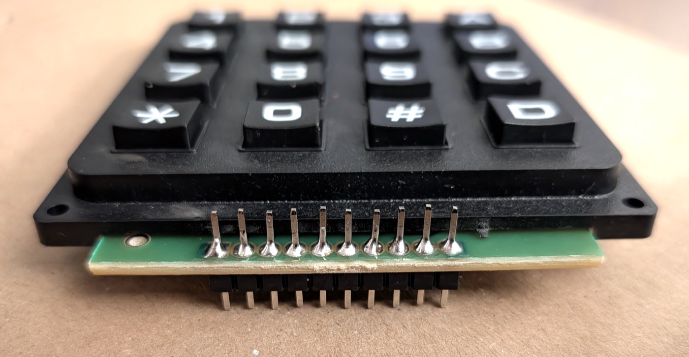
Once soldered, the pins were too short to hold a female Dupont. Half a male-male Dupont wire soldered onto each pin makes a flexible cable.
Map the connector (15 min). The contacts are conductive rubber, so continuity mode stays silent. Use the Ω range instead: hold a key, probe two connector pins, and look for a low reading. On this keypad:
| Connector pin | 1 | 2 | 3 | 4 | 5 | 6 | 7 | 8 | 9 | 10 |
|---|---|---|---|---|---|---|---|---|---|---|
| Role | — | C1 | C2 | C3 | C4 | L1 | L2 | L3 | L4 | — |
Wiring
| Keypad | L1 | L2 | L3 | L4 | C1 | C2 | C3 | C4 |
|---|---|---|---|---|---|---|---|---|
| Pico | GP9 | GP8 | GP7 | GP6 | GP13 | GP12 | GP11 | GP10 |
How the scan works. Rows are outputs, held at 1. Columns are inputs with a pull-up, so they read 1 at rest. To test a row, drive it to 0 and read the columns: a column reading 0 has a pressed key on that row.
from machine import Pin
import time

KEYS = [
    ["1", "2", "3", "A"],
    ["4", "5", "6", "B"],
    ["7", "8", "9", "C"],
    ["*", "0", "#", "D"],
]

rows = [Pin(n, Pin.OUT, value=1) for n in (9, 8, 7, 6)]
columns = [Pin(n, Pin.IN, Pin.PULL_UP) for n in (13, 12, 11, 10)]


def pressed_key():
    found = None
    for row, labels in zip(rows, KEYS):
        row.value(0)
        for column, label in zip(columns, labels):
            if column.value() == 0:
                found = label
        row.value(1)
    return found


previous = None
while True:
    key = pressed_key()
    if key is not None and key != previous:
        print("Key:", key)
    previous = key
    time.sleep_ms(20)
Test. All 16 keys print their own name, once per press. The 20 ms pause is the debounce: a contact bounces for a few milliseconds when it closes, and sampling slower than that sees one clean press.
6. The buzzer
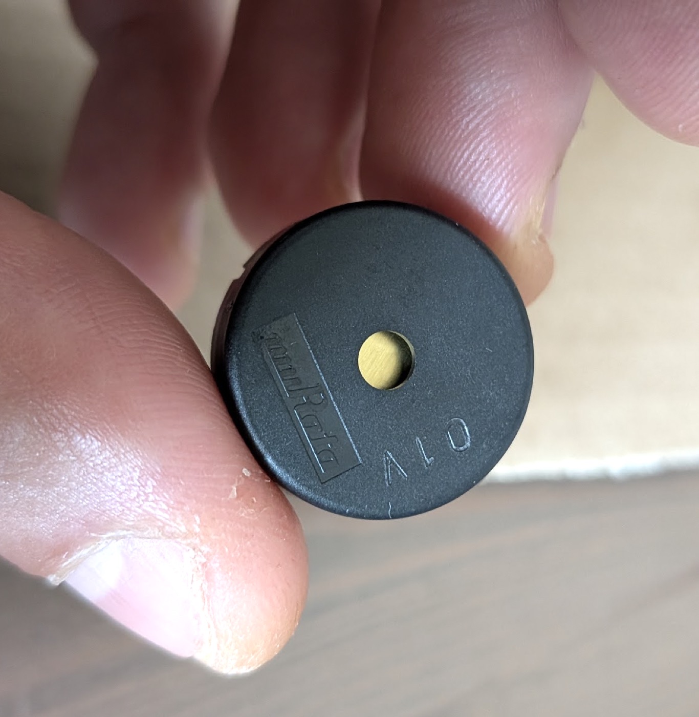
This buzzer is passive: it has no oscillator inside. The Pico makes the sound itself with PWM, switching a pin on and off thousands of times per second. It is loudest at its resonant frequency, 4 kHz.
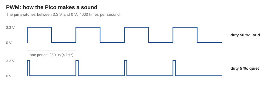
Wiring: GP0 → 220 Ω → one leg, other leg → GND. The resistor limits the current spikes a piezo draws on each edge.
Test.
from machine import Pin, PWM
import time

buzzer = PWM(Pin(0))
buzzer.freq(4000)
buzzer.duty_u16(32768)
time.sleep(0.3)
buzzer.duty_u16(0)
duty_u16(32768) keeps the pin high half of the time. Try freq(2000) or duty_u16(3000) and hear the difference.
7. The OLED screen
A 128×64 pixel screen, driven over I2C: two wires, data (SDA) and clock (SCL), shared by any number of devices, each with an address.
Labels vary
On this module, VDD means VCC (power) and SCK means SCL (clock).
Wiring: SDA → GP26, SCK → GP27, VDD → 3V3, GND → GND.
Find it on the bus.
from machine import Pin, I2C
i2c = I2C(1, sda=Pin(26), scl=Pin(27))
print(i2c.scan())
[60] means one device at address 0x3C: the screen.
Install the driver. Save ssd1306.py, from micropython-lib, on the Pico under the same name, the same way as the RC522 driver.
Test.
from machine import Pin, I2C
from ssd1306 import SSD1306_I2C

screen = SSD1306_I2C(128, 64, I2C(1, sda=Pin(26), scl=Pin(27)))
screen.fill(0)
screen.text("Warden", 0, 0)
screen.text("Show your badge", 0, 24)
screen.show()
8. Everything on one breadboard
With five modules on Dupont wires next to the Pico, the prototype was a tangle. This part moves everything onto one large breadboard, one module at a time, with a test after each.
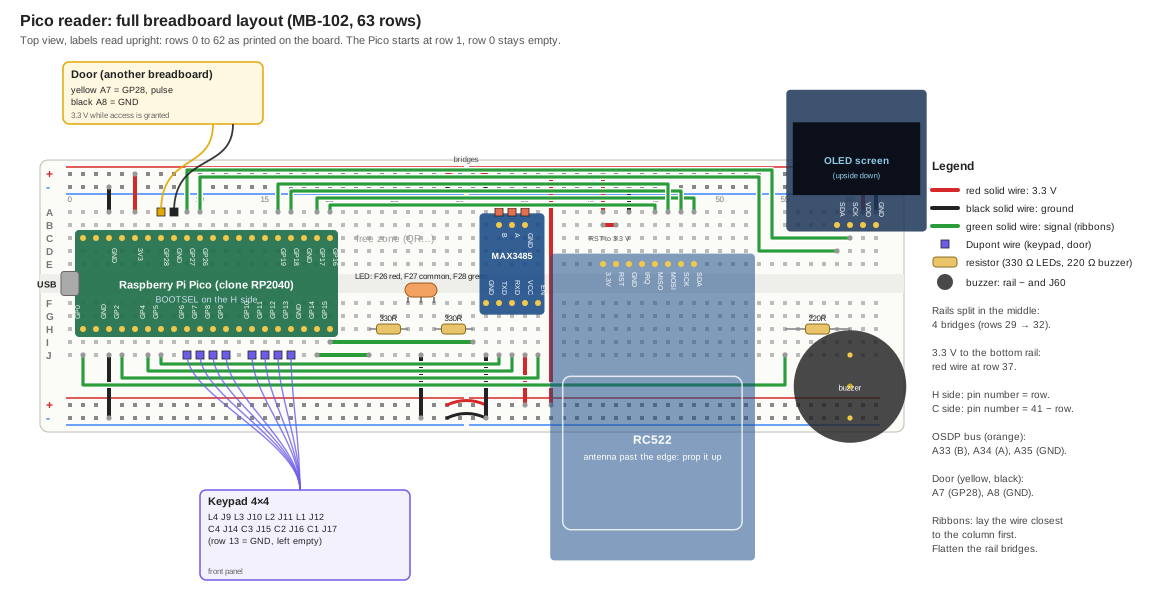
How to read the breadboard
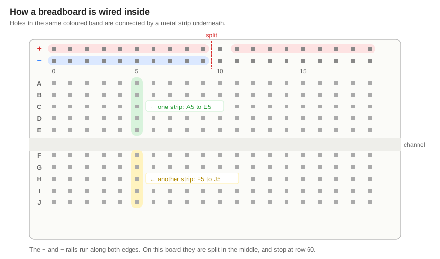
- Rows are numbered 0 to 62 along the top. Use the numbers printed at the top, read upright. The bottom ones are upside down and reversed.
- Columns are lettered
AtoE(top half) andFtoJ(bottom half), read on the left. - One row, one half: one strip. The 5 holes
A–Eof a row are connected. So areF–J. The two halves are not connected. - Rails run along the edges:
+(red line) and−(blue line). On this board they are split in the middle and stop at row 60.
The Pico sits across the centre channel, columns C and H, rows 1 to 20, USB on the left. On the H side (BOOTSEL side), the pin number is the row number. On the C side, the pin number is 41 minus the row.
Count on the board, not on a photo
Every placement error in this build came from counting holes on a photo. Count on the breadboard itself, with a finger, from a known landmark such as the last pin of the Pico.
The design rules
The Pico is a wall. It covers columns C to H on rows 1 to 20. Only two columns stay free on each side (A–B, I–J). Every signal leaves through them.
Signals travel in ribbons. Each signal wire starts at column A (or J), rises onto the smooth strip between the column and the rail, runs along the board, and drops down to its module. Laid side by side, they form a ribbon: 6 wires along the top, 4 along the bottom.
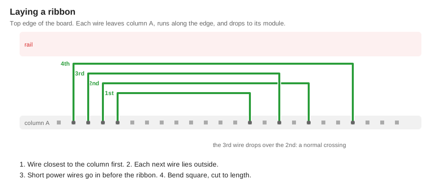
Ribbon rules
- Short power wires go in first. The ribbons lie over them.
- Flatten the rail bridges so the ribbon can lie over them.
- Lay the wire closest to the column first. Each next wire lies outside the previous one.
- Cut each wire to length, strip 5 mm at each end, bend it square at every corner. Dry-fit before cutting.
- A few crossings are fine. The last wire laid goes over.
Pins were chosen so wires barely cross. That is why the buzzer is on GP0, the RS-485 link on UART1, and the RC522's RST is tied to 3.3 V instead of a GPIO: each of those removed several crossings.
Two modules are planted upside down. Their boards would otherwise cover the ribbons. The RC522's antenna hangs past the bottom edge, away from the metal strips that would shorten its range: prop it up. The screen's board hangs past the top edge, and two commands flip the display back.
Colour code: red for 3.3 V, black for ground, green for every signal.
Final pin map
| Function | Pico pins |
|---|---|
| Bicolor LED | GP14 red, GP15 green |
| RC522 (SPI0) | GP16 MISO, GP17 SDA, GP18 SCK, GP19 MOSI. RST tied to 3.3 V |
| Keypad | GP9–GP6 rows L1–L4, GP13–GP10 columns C1–C4 |
| Buzzer (PWM) | GP0 |
| OLED (I2C1) | GP26 SDA, GP27 SCL |
| MAX3485 (UART1) | GP4 TX, GP5 RX, GP2 transmit enable |
| Door pulse | GP28 (added in part 10) |
| Free | GP1, GP3, GP20, GP21, GP22 |
Step 1: rails and power (30 min)
- Bridge each rail across its split, near rows 29 to 32: red on
+, black on−. - Continuity test: each rail beeps end to end.
+and−never beep together. - Plant the Pico: columns
CandH, rows 1 to 20, USB on the left. - Power wires:
| Wire | From | To |
|---|---|---|
| red | A5 (3V3) | top rail + |
| black | A3 (GND) | top rail − |
| black | J3 (GND) | bottom rail − |
| red | top rail +, row 37 | bottom rail +, row 37, straight across |
Test: about 3.3 V between + and −, on each rail, on both sides of the split.
Step 2: the LED (15 min)
| What | Holes |
|---|---|
| LED red, common, green | F26, F27, F28 |
| 330 Ω, red | H23–H26 |
| 330 Ω, green | H28–H31 |
green wire, GP14 | J19–J23 |
green wire, GP15 | I20–I31 |
| black wire, common | J27 → bottom rail − |
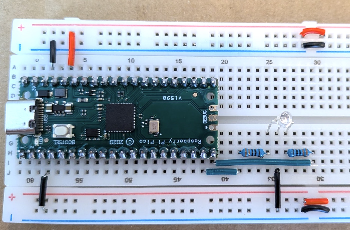
Test: the LED blinks red then green.
Step 3: the keypad (10 min)
The only module left on Dupont wires: it belongs on a front panel.
| Keypad | L4 | L3 | L2 | L1 | — | C4 | C3 | C2 | C1 |
|---|---|---|---|---|---|---|---|---|---|
| Hole | J9 | J10 | J11 | J12 | row 13 empty (GND) | J14 | J15 | J16 | J17 |
Test: the scan program prints all 16 keys.
Step 4: the MAX3485 (30 min)
The MAX3485 turns the Pico's UART into RS-485: a voltage difference between two wires, A and B, that carries hundreds of metres and shrugs off noise. It does not know OSDP. It only converts.
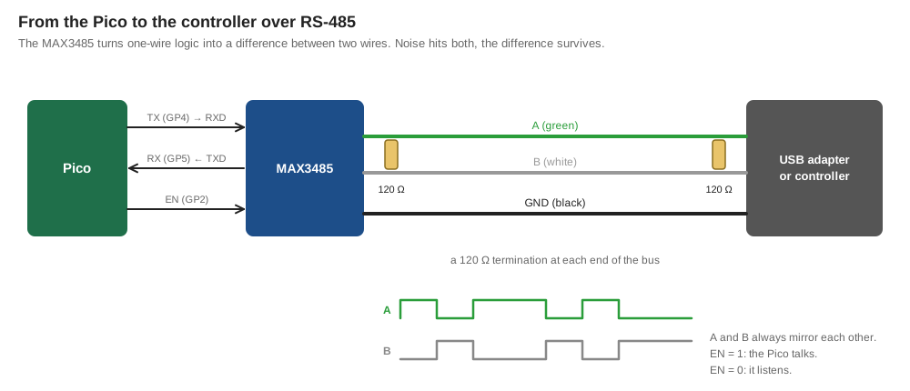
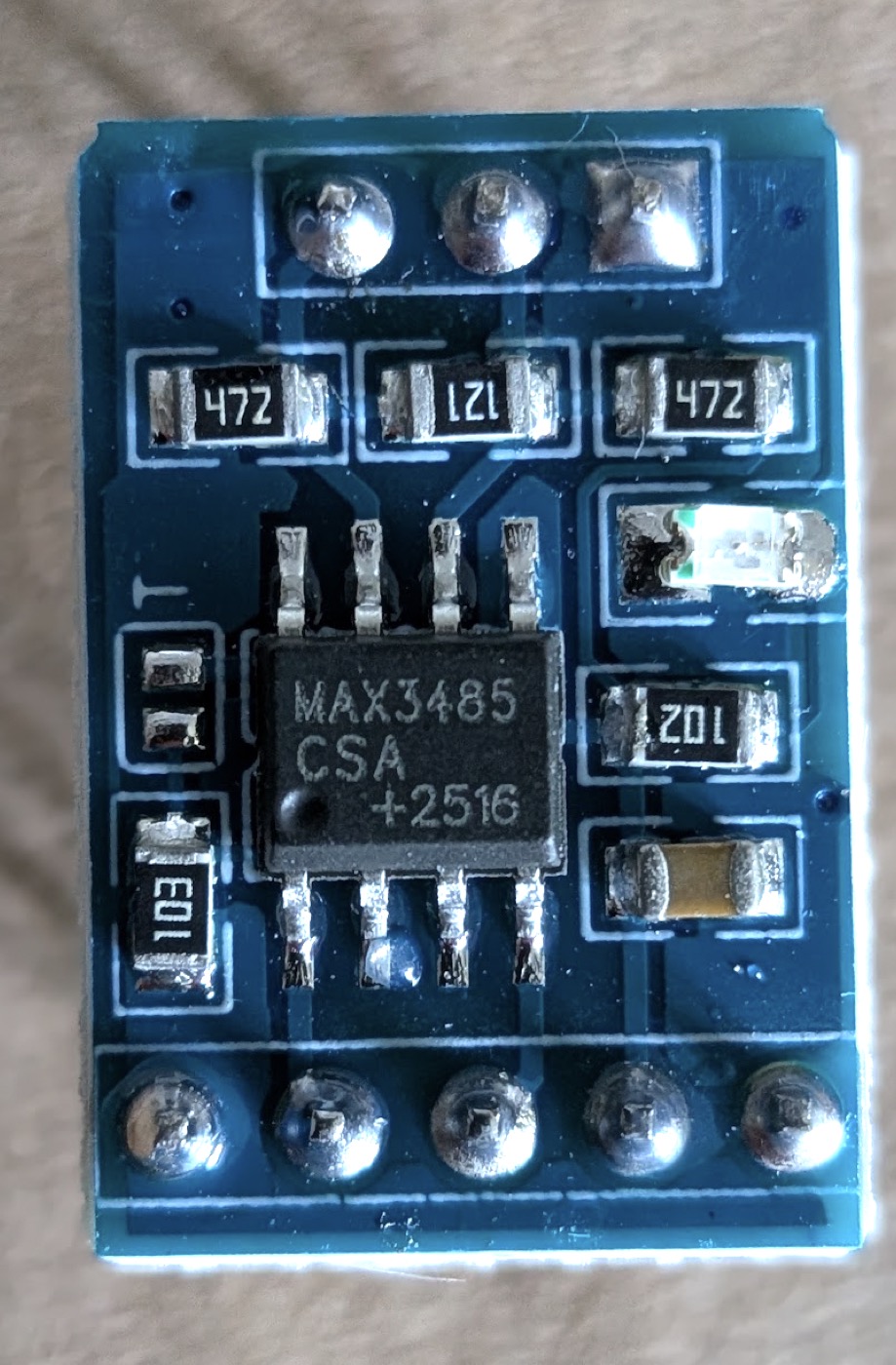
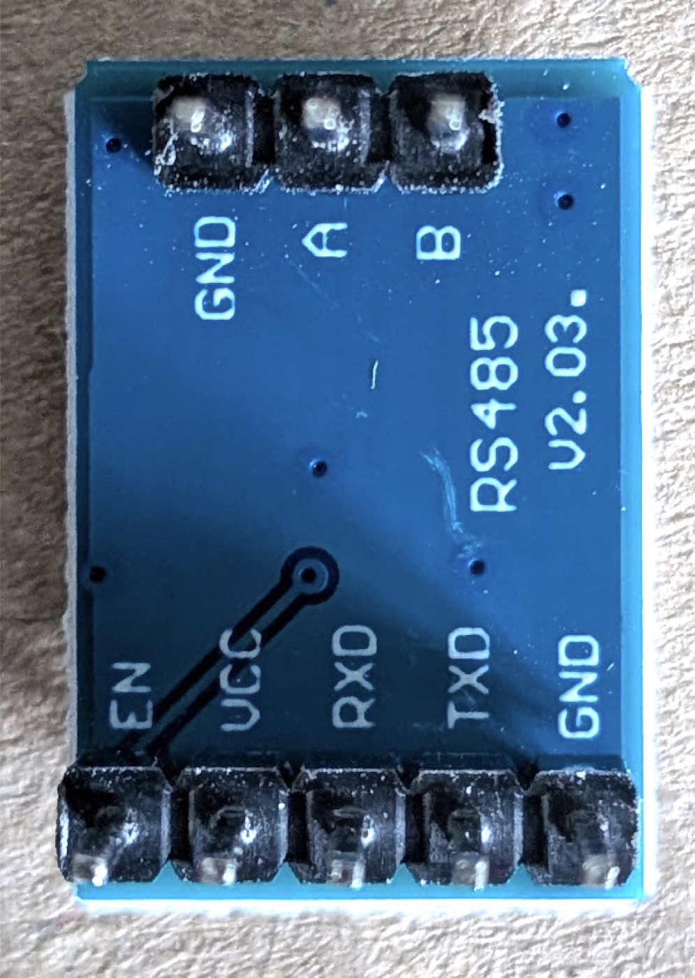
First, check the pin roles (10 min). TXD and RXD do not say which way data flows. The chip does: leg 1 (RO) outputs what comes from the bus, leg 4 (DI) takes what goes to the bus, legs 2 and 3 set the direction.
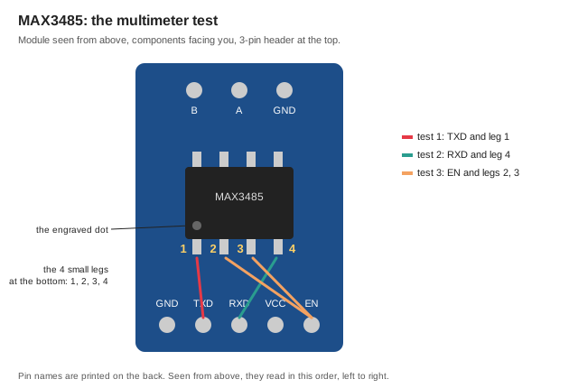
All three tests beep: TXD goes to the Pico's RX, RXD comes from the Pico's TX.
Plant it. Its two headers face each other 6 holes apart, so it straddles the channel like the Pico. Components up, 3-pin header towards the top.
| What | Holes |
|---|---|
GND, TXD, RXD, VCC, EN | F32–F36 |
B, A, GND | B33–B35 |
| black wire | J32 → bottom rail − |
| red wire | J35 → bottom rail + |
Bottom ribbon, in laying order:
| Wire | From | To |
|---|---|---|
1. GP5 (RX) ← TXD | J7 | J33 |
2. GP4 (TX) → RXD | J6 | J34 |
3. GP2 → EN | J4 | J36 |
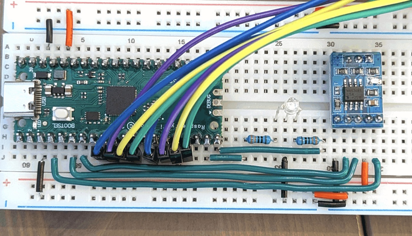
Test: about 3.3 V between H35 and H32. The module's red LED is on.
The meter reads 0 V
Push the probe deeper, down to the metal strip inside the hole.
Step 5: the buzzer (20 min)
Planted directly: one leg in the last hole of the bottom − rail (row 60), the other in J60. Its legs are 4 holes apart, which is exactly the distance from J to the outer rail.
| What | Holes |
|---|---|
| buzzer | bottom rail − (row 60) and J60 |
| 220 Ω | H55–H60 |
4th bottom ribbon wire, GP0 | J1 → J55, outside the MAX3485 wires |
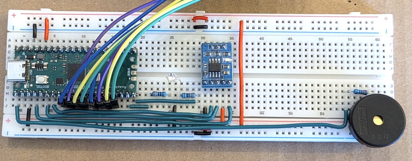
Test: the beep program, with PWM(Pin(0)).
Step 6: the RC522 (30 min)
Upside down in column E, rows 41 to 48, edge to edge with the MAX3485. Seen from above, the pins read 3.3V, RST, GND, IRQ, MISO, MOSI, SCK, SDA from left to right.
| What | Holes |
|---|---|
| RC522 | E41–E48 |
| red wire, 3.3 V | A41 → top rail + |
| black wire, ground | A43 → top rail − |
red wire, RST to 3.3 V | B41–B42 |
Top ribbon, first four wires, in laying order:
| Wire | From | To |
|---|---|---|
1. GP16 → MISO | A20 | A45 |
2. GP17 → SDA | A19 | A48 |
3. GP18 → SCK | A17 | A47 |
4. GP19 → MOSI | A16 | A46 |
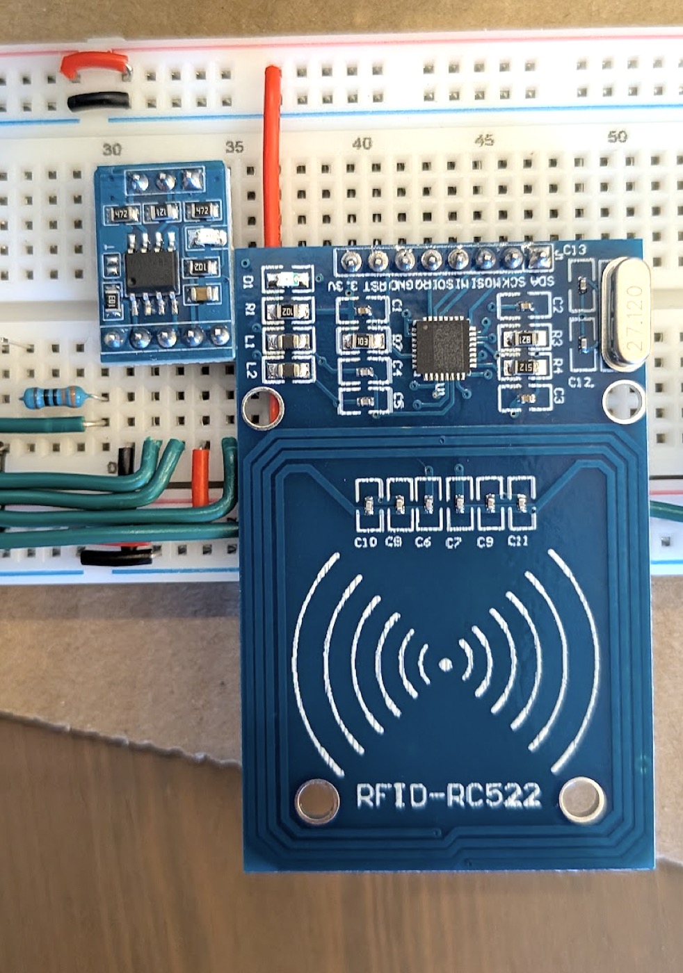
With RST tied high, the RC522 stays on, and the driver resets it by command at every init(). The code still says rst=20: GP20 is simply not connected anymore.
Test: the badge program prints your UID. Range here: about 4 cm, against 5 cm off the board.
Step 7: the screen (20 min)
Upside down in column B, rows 59 to 62, its board over the top rails. Seen from above: SDA, SCK, VDD, GND.
| What | Holes |
|---|---|
| screen | B59–B62 |
| red wire | A61 → last hole of the top rail +, bent |
| black wire | A62 → last hole of the top rail −, bent |
5. GP26 → SDA | A10, drops at row 53 into column D, ends at D59 |
6. GP27 → SCK | A9, drops at row 54 into column C, ends at C60 |
Lay the power wires before planting the screen: they slide under its board.
Test: i2c.scan() returns [60]. Then flip the display:
screen.write_cmd(0xA0)
screen.write_cmd(0xC0)
The first command mirrors left and right, the second top and bottom.
9. The full program
One loop handles both the keypad and the badge. The PIN is 1234, and one badge is known.
flowchart TD
    S["Show 'Enter PIN or show badge'"] --> L{"Every 20 ms"}
    L --> K["Scan the keypad"]
    K -->|"digit"| T["Add it to the PIN, show a star"]
    K -->|"#"| D["decide(PIN == 1234)"]
    K -->|"*"| C["Clear the PIN"]
    L --> P{"100 ms since the last poll?"}
    P -->|"yes"| R["Ask the RC522 for a badge"]
    R -->|"new badge"| B["decide(badge is known)"]
    R -->|"no badge 5 times"| F["Forget the last badge"]
    D --> G["Granted: green, long beep"]
    D --> X["Denied: red, three beeps"]
    B --> G
    B --> X
from machine import Pin, PWM, I2C
import time
from mfrc522 import MFRC522
from ssd1306 import SSD1306_I2C
KEYS = [
["1", "2", "3", "A"],
["4", "5", "6", "B"],
["7", "8", "9", "C"],
["*", "0", "#", "D"],
]
PIN_CODE = "1234"
KNOWN_BADGE = [0x6B, 0xAD, 0x30, 0x8E]
BADGE_POLL_MS = 100
BADGE_GONE_AFTER_MISSES = 5
rows = [Pin(n, Pin.OUT, value=1) for n in (9, 8, 7, 6)]
columns = [Pin(n, Pin.IN, Pin.PULL_UP) for n in (13, 12, 11, 10)]
red = Pin(14, Pin.OUT)
green = Pin(15, Pin.OUT)
buzzer = PWM(Pin(0))
buzzer.freq(4000)
reader = MFRC522(spi_id=0, sck=18, mosi=19, miso=16, cs=17, rst=20)
screen = SSD1306_I2C(128, 64, I2C(1, sda=Pin(26), scl=Pin(27)))
screen.write_cmd(0xA0)
screen.write_cmd(0xC0)
def pressed_key():
found = None
for row, labels in zip(rows, KEYS):
row.value(0)
for column, label in zip(columns, labels):
if column.value() == 0:
found = label
row.value(1)
return found
def read_badge():
reader.init()
status, _ = reader.request(reader.REQIDL)
if status == reader.OK:
status, uid = reader.SelectTagSN()
return uid if status == reader.OK else None
def beep(milliseconds):
buzzer.duty_u16(32768)
time.sleep_ms(milliseconds)
buzzer.duty_u16(0)
def beeps(count, milliseconds):
for _ in range(count):
beep(milliseconds)
time.sleep_ms(milliseconds)
def display(*lines):
screen.fill(0)
for number, line in enumerate(lines):
screen.text(line, 0, number * 16)
screen.show()
def show_idle():
display("Enter PIN", "or show badge")
def grant_access():
display("Access granted")
green.value(1)
beep(600)
time.sleep_ms(900)
green.value(0)
def deny_access():
display("Access denied")
red.value(1)
beeps(3, 120)
time.sleep_ms(800)
red.value(0)
def decide(allowed):
if allowed:
grant_access()
else:
deny_access()
show_idle()
typed = ""
previous_key = None
previous_badge = None
misses = 0
last_poll = time.ticks_ms()
show_idle()
while True:
key = pressed_key()
if key is not None and key != previous_key:
beep(40)
if key == "#":
decide(typed == PIN_CODE)
typed = ""
elif key == "*":
typed = ""
show_idle()
else:
typed += key
display("PIN:", "*" * len(typed))
previous_key = key
if time.ticks_diff(time.ticks_ms(), last_poll) >= BADGE_POLL_MS:
last_poll = time.ticks_ms()
uid = read_badge()
if uid is None:
misses += 1
if previous_badge is not None and misses > BADGE_GONE_AFTER_MISSES:
print("Badge removed")
previous_badge = None
else:
misses = 0
if uid != previous_badge:
previous_badge = uid
print("Badge:", reader.tohexstring(uid))
decide(uid == KNOWN_BADGE)
typed = ""
time.sleep_ms(20)
What to notice
- One loop, two inputs. The keypad is read every 20 ms. The RC522 is slower, so
ticks_difflimits it to every 100 ms. decideis the only place that grants or denies, whether the request came from the keypad or a badge. In wardn, that is exactly the part that moves to the controller.- A badge left on the reader triggers once. It is forgotten after half a second without a read.
- Why not use the Pico's second core? The loop is busy less than 10 % of the time, and two cores sharing the screen and buzzer would need locks. One loop is simpler and fast enough.
Test
1234#: green, long beep, "Access granted".- Any other code: red, three beeps, "Access denied".
*clears. - The known badge is granted, another badge is denied.
10. Open the door
A reader that says "Access granted" and opens nothing is not much use. Here, the reader sends a pulse: one pin goes to 3.3 V while the green LED is on, then back to 0 V.
The pulse goes to a second breadboard that plays the door. That door has its own build log, 20. A DIY door: it will open either on this direct pulse or on an OSDP command. This part only builds the reader's side.
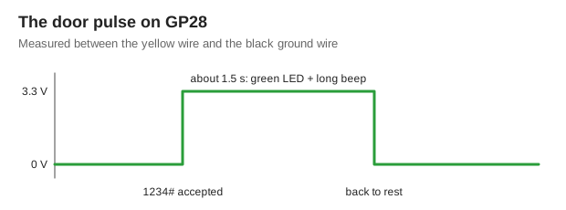
Two wires (10 min). GP28 is free, and the pin next to it is a ground. Both are on the C side of the Pico:
| Wire | Hole | Pico pin |
|---|---|---|
| yellow, signal | A7 | pin 34, GP28 |
| black, ground | A8 | pin 33, GND |
The ground travels with the signal. A voltage is always measured between two points, so the door needs the reader's ground to make sense of its 3.3 V.
The code (10 min). In the full program, add the pin and raise it in grant_access():
door = Pin(28, Pin.OUT, value=0)


def grant_access():
    display("Access granted")
    green.value(1)
    door.value(1)
    beep(600)
    time.sleep_ms(900)
    door.value(0)
    green.value(0)
value=0 matters: the door stays closed from power-up until someone is accepted.
Test: meter on 20 V DC between the two free ends. 0 at rest, about 3.3 after 1234#, still 0 after a wrong code.
One hand for the meter, one for the keypad
Plant both free ends in a small spare breadboard. The probes stay in by themselves.
11. The bus: plain text both ways
Before OSDP, a simpler test: plain text over the bus, first from the Pico to the laptop, then back. It proves the wires, the transmit-enable pin and the speed.
Wire the bus (15 min). Three male-male Dupont wires, from the breadboard to the adapter's screw terminals, adapter unplugged:
| Wire | Hole | Adapter |
|---|---|---|
green, A | A34 | A+ |
white, B | A33 | B- |
| black, ground | A35 | GND |
There is no official colour standard for RS-485 or OSDP. Green and white for data is a habit inherited from Wiegand readers.
Find the port. Run ls /dev/tty.* before and after plugging the adapter into the Mac. The new line is the adapter. Here it was /dev/tty.usbmodem5ACC0227761: the long number is the adapter's serial. The Pico itself shows up as another usbmodem, with a short number.
flowchart LR
    subgraph Mac
        T["Thonny"]
        S["screen / picocom<br/>or controller.py"]
    end
    subgraph Pico
        PR["print()"]
        U["uart.write()"]
    end
    PR -- "USB: tty.usbmodem1101" --> T
    U -- "GP4 → MAX3485 → A/B → adapter<br/>tty.usbmodem5ACC0227761" --> S
Two ports, two roads. print() goes over USB to Thonny. uart.write() goes over the bus, and only a program reading the adapter's port sees it. That is the controller's seat.
From the Pico to the Mac (15 min). The Pico raises GP2 to talk, writes, waits for the last byte to leave, and lowers GP2 to listen again:
from machine import Pin, UART
import time

uart = UART(1, baudrate=9600, tx=Pin(4), rx=Pin(5))
transmit_enable = Pin(2, Pin.OUT, value=0)


def send(text):
    transmit_enable.value(1)
    uart.write(text)
    uart.flush()
    transmit_enable.value(0)


count = 0
while True:
    print("sent hello", count)
    send("hello {}\r\n".format(count))
    count += 1
    time.sleep(1)
On the Mac, read the adapter's port:
picocom -b 9600 /dev/tty.usbmodem5ACC0227761
screen /dev/tty.usbmodem5ACC0227761 9600 does the same and is already installed. Quit picocom with Ctrl-A then Ctrl-X, screen with Ctrl-A, K, Y.
Test: hello 0, hello 1… scroll, one per second.
Garbage, one burst per second
A and B are crossed: the signal arrives upside down. Swap the green and white wires. Some vendors call A what others call B. Here, the first wiring was right, and swapping it caused the garbage.
From the Mac to the Pico (15 min). The reverse: what you type in picocom shows on the OLED, and Enter clears it.
from machine import Pin, UART, I2C
from ssd1306 import SSD1306_I2C

uart = UART(1, baudrate=9600, tx=Pin(4), rx=Pin(5))
transmit_enable = Pin(2, Pin.OUT, value=0)
screen = SSD1306_I2C(128, 64, I2C(1, sda=Pin(26), scl=Pin(27)))
screen.write_cmd(0xA0)
screen.write_cmd(0xC0)


def display(text):
    screen.fill(0)
    screen.text("Received:", 0, 0)
    screen.text(text[-16:], 0, 24)
    screen.show()


received = ""
display(received)
while True:
    if uart.any():
        for byte in uart.read():
            received = "" if byte == 13 else received + chr(byte)
        display(received)
Test: letters typed on the Mac appear on the reader's screen.
12. Talking OSDP
The rule never changes: the controller talks, the reader answers. The reader never speaks first. Each controller message is a command, each reader message is a reply, and both travel as the same kind of frame.
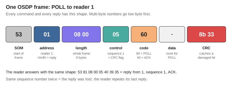
Two files do the work, both in All the code. The reader also needs the fixed RC522 driver from part 4: the original one is too slow to answer in time.
osdp.pybuilds and reads frames. The same file runs on the Pico and on the Mac, and it produces the same bytes asedge/wardn-osdp, the real controller's OSDP code. Its CRC is checked against the standard's check value.controller.pyplays the controller from the Mac, through the adapter. Plain Python 3, nothing to install.
Copy osdp.py onto the Pico with Thonny (File → Open → This computer, then Save as… → Raspberry Pi Pico). Close picocom before running python3 controller.py: a serial port opens only once, and the second program gets Resource busy.
sequenceDiagram
    participant C as Controller (Mac)
    participant R as Reader (Pico)
    C->>R: ID
    R-->>C: PDID: who I am
    C->>R: CAP
    R-->>C: PDCAP: what I can do
    loop every second
        C->>R: POLL
        alt nothing new
            R-->>C: ACK
        else badge waiting
            R-->>C: RAW: 6B AD 30 8E
        else keys waiting
            R-->>C: KEYPAD: 1234#
        end
    end
Step 1: POLL and ACK (30 min)
The smallest possible conversation. The heart of the reader is a table: a command comes in, a reply goes out. An unknown command gets NAK with reason 3, "unknown command".
REPLIES = {
    osdp.POLL: (osdp.ACK, b""),
}


def answer(command):
    return REPLIES.get(command.code, (osdp.NAK, bytes([3])))


buffer = b""
while True:
    if uart.any():
        buffer += uart.read()
    command, buffer = osdp.parse(buffer)
    if command is not None and command.address == 1:
        code, data = answer(command)
        send(osdp.reply(1, command.sequence, code, data))
Test:
-> 53 01 08 00 04 60 ba 00
<- ACK, sequence 0
-> 53 01 08 00 05 60 8b 33
<- ACK, sequence 1
The sequence runs 0, then 1, 2, 3 and round again. 0 tells the reader the controller just started.
Step 2: ID and CAP (20 min)
When a controller discovers a reader, it asks two questions. ID: who are you? CAP: what can you do? Two more lines in the table:
IDENTITY = bytes([0x00, 0x00, 0x00, 1, 1]) + unique_id()[-4:] + bytes([0, 1, 0])
CAPABILITIES = bytes([
    3, 1, 0,
    4, 4, 1,
    5, 2, 1,
    6, 1, 1,
    8, 1, 0,
    10, 128, 0,
])

REPLIES = {
    osdp.POLL: (osdp.ACK, b""),
    osdp.ID: (osdp.PDID, IDENTITY),
    osdp.CAP: (osdp.PDCAP, CAPABILITIES),
}
The serial number comes from the chip: every RP2040 has a unique ID burned in. The vendor is 00 00 00, because a real vendor has an assigned number and a hobbyist does not. Each capability is three bytes: function, level, count.
Test:
<- PDID, sequence 0: vendor 00 00 00, model 1, version 1, serial 1c879238, firmware 0.1.0
<- PDCAP, sequence 1:
     card data format: compliance 1, count 0
     reader LED control: compliance 4, count 1
     reader buzzer: compliance 2, count 1
     reader text output: compliance 1, count 1
     check character support: compliance 1, count 0
     receive buffer size: compliance 128, count 0
The serial 1c879238 is the same chip ID the Mac shows as the Pico's USB serial, read backwards.
Step 3: badge and keypad go up (30 min)
Since the reader never speaks first, a badge or a key waits in a queue until the next POLL. The reader then answers with the event instead of ACK:
RAW(0x50): a badge. Reader number, format (0= raw bits), bit count, then the badge's UID.KEYPAD(0x53): keys. Reader number, key count, then the keys as text.
The reader no longer knows whether the PIN is right or the badge is known. PIN_CODE, KNOWN_BADGE and decide() are gone: that is the controller's job now. It still beeps on each key, like every reader on the market.
def answer(command):
    global pending_keys
    if command.code == osdp.POLL and pending_badges:
        return badge_reply(pending_badges.pop(0))
    if command.code == osdp.POLL and pending_keys:
        keys, pending_keys = pending_keys, ""
        return keys_reply(keys)
    return REPLIES.get(command.code, (osdp.NAK, UNKNOWN_COMMAND))


def handle(command):
    global last_sequence, last_reply
    repeated = command.sequence == last_sequence and command.sequence != 0
    if not repeated:
        code, data = answer(command)
        last_reply = osdp.reply(ADDRESS, command.sequence, code, data)
    last_sequence = command.sequence
    send(last_reply)
handle() covers a detail of the protocol. When the controller sends the same sequence number twice, its reply got lost. The reader sends its last reply again, without taking the next event from the queue. Without it, a lost badge would never reach the controller.
Test:
<- KEYPAD, sequence 3: reader 0, keys 1
<- KEYPAD, sequence 1: reader 0, keys 2
<- RAW, sequence 2: reader 0, format 0, 32 bits: 6B AD 30 8E
Replies one POLL late, keys lost
With the original RC522 driver, only one key in four reached the controller, and each reply carried the previous command's sequence number. The reader answered after more than 200 ms, OSDP's limit, which the real controller (wardn-edge) also enforces, so the controller dropped the late replies and the keys in them. The driver's wait loop spun while no badge was present. With the fixed driver, every key arrives.
Step 4: the controller decides (30 min)
The last piece: the controller answers. On a good PIN or a known badge, it sends three commands, the same three the real controller sends:
| Command | Granted | Denied |
|---|---|---|
LED (0x69) | green for 2 s | red for 2 s |
BUZ (0x6A) | one short beep | three long beeps |
TEXT (0x6B) | "Access granted" | "Access denied" |
It also shows PIN: *** while the PIN is typed, and puts "Badge or PIN" back 2 seconds after a decision. The reader only obeys.
The LED and the buzzer now run in the background. Three long beeps last more than a second, and a reader that blocks while beeping misses the 200 ms limit. So the buzzer only remembers when to switch next:
class Buzzer:
    def command(self, data):
        tone, on, off, count = data[1], data[2], data[3], data[4]
        self.on_ms, self.off_ms = on * 100, off * 100
        self.edges_left = 2 * count if tone == osdp.TONE_DEFAULT else 0
        self.next_edge = time.ticks_ms()

    def refresh(self):
        if self.edges_left > 0 and time.ticks_diff(time.ticks_ms(), self.next_edge) >= 0:
            sounding = self.edges_left % 2 == 0
            buzzer.duty_u16(32768 if sounding else 0)
            self.next_edge = time.ticks_add(time.ticks_ms(), self.on_ms if sounding else self.off_ms)
            self.edges_left -= 1
The main loop calls refresh() every few milliseconds, between two bus reads. The full program is 12-4-controller-decides.py.
Test:
<- KEYPAD, sequence 2: reader 0, keys 4#
   decision: Access granted
-> LED 53 01 16 00 07 69 …
<- ACK, sequence 3
-> BUZ 53 01 0d 00 05 6a …
<- ACK, sequence 1
-> TEXT 53 01 1c 00 06 6b …
<- ACK, sequence 2
1234# or the known badge: green, one beep, "Access granted". Anything else: red, three beeps, "Access denied".
What the reader understands
| Command | Code | The reader… | Reply |
|---|---|---|---|
POLL | 0x60 | says "nothing new", or sends a waiting event | ACK, RAW, KEYPAD |
ID | 0x61 | says who it is | PDID |
CAP | 0x62 | says what it can do | PDCAP |
LED | 0x69 | lights red, green or amber, for a set time | ACK |
BUZ | 0x6A | beeps N times, in the background | ACK |
TEXT | 0x6B | shows a line on the OLED | ACK |
| anything else | refuses, with reason 3, "unknown command" | NAK |
Left out on purpose:
OUT: opening the door is the door's job, over its own OSDP address.COMSET: the reader stays at address 1 and 9600 baud.LSTAT,ISTAT,OSTAT,RSTAT: the reader has no tamper switch and no inputs of its own.- Secure Channel (
KEYSET,CHLNG,SCRYPT): AES encryption, for the Rust version. - File transfer, biometrics, advanced smart cards: no hardware for them. The RC522 only reads the badge's number.
13. What comes next
The reader is finished: it reads badges and PINs, and speaks OSDP to a controller that decides. The next steps grow it in two directions.
Towards production
- The real controller.
wardn-edgeon a Raspberry Pi, in place ofcontroller.py, on the same bus. - Rust firmware. The MicroPython prototype moves to Rust with embassy, reusing the
wardn-osdpcrate, so the reader and the controller share one implementation of the protocol. The Secure Channel comes with it.
New ways to identify someone
- A QR code reader. A second reader on the same bus, for visitors: a QR code on a phone instead of a badge.
- ANPR. A camera reads a car's number plate and hands it to the controller already read, as a credential, the same way a badge number arrives over OSDP.
- Virtual badges over Bluetooth Low Energy. A phone carries the badge and exchanges it with the reader over BLE, with no card at all. It needs a board with a radio, such as a Pico W: the clone used here has none.
What went wrong, and the fix
| Symptom | Cause | Fix |
|---|---|---|
| The Pico does not match the shopping list | A USB-C clone, no RESET button | Identify the chip (RP2-B2 is an RP2040). BOOTSEL: unplug, hold, replug |
No badge detected, version register reads 0x84 | Driver bug: b'%c' % value makes two bytes from 0x80 up | Use bytes([value]) |
| Keys reach the controller only one time in four | Driver bug: the RC522 wait loop ignores its timer and blocks the Pico when no badge is present, so replies miss the 200 ms limit | The fixed mfrc522.py: the loop stops on the timer |
| The same badge prints over and over | The RC522 misses some reads | Forget a badge only after several misses in a row |
Run in Thonny does not show an expression's value | That only happens in the Shell | Use print(...) |
| The keypad has no copper on the back | Single-sided board | Solder on the key side |
| Female Dupont connectors fall off the keypad | Pins too short after soldering | Solder half male-male Dupont wires |
| Continuity mode never beeps on a key | Conductive rubber contacts | Use the Ω range |
| The keypad looked scrambled | One bad measurement | Redo a doubtful measurement before drawing conclusions |
220R printed on a resistor | R stands for Ω | 220 Ω |
| The "orange" is almost red | Green is dimmer at the same current | Balance with the resistor values if it matters |
| Breadboard numbers printed twice, once upside down | Printed for either orientation | Read only the top numbers and the left letters |
| Dupont wires everywhere | The Pico only leaves two free columns per side | Ribbons of solid wire along the edges, pins chosen to avoid crossings |
| Modules cover the ribbons | Boards wider than the free space | Plant them upside down, overhanging the opposite edge |
| A module one row off the plan | The plan was drawn from a photo | Count on the breadboard, then update the plan |
| The meter reads 0 V on a powered module | Probe not touching the metal strip | Push it deeper |
Two usbmodem ports appear | One is the Pico, one the adapter | The long serial number is the adapter |
screen quits at once with [screen is terminating] | The port name was copied from an example | Use the real name, or complete it with Tab |
| The bus program shows nothing in Thonny | It writes to the bus, not to USB | Read the adapter's port with picocom or screen |
| Garbage, one burst per second | A and B crossed | Swap green and white |
Resource busy on the adapter's port | picocom still had it open | Close picocom first: a port opens only once |
| Every OSDP reply arrives one POLL late | The reader answers after more than 200 ms | Same cause as the lost keys: the fixed mfrc522.py |
Glossary
| Word | Meaning |
|---|---|
| GPIO | A chip pin the program can set to 3.3 V or 0 V, or read |
| BOOTSEL | Boot mode where the Pico shows up as a USB drive to receive firmware |
| REPL | The prompt where each line of Python runs on the Pico right away |
| Pull-up | An internal resistor that holds an input at 1 when nothing drives it |
| Debounce | Ignoring the few milliseconds a contact bounces when it closes |
| PWM | Switching a pin on and off fast, to make a sound or dim a light |
| SPI | A 4-wire bus: clock, data out, data in, chip select |
| I2C | A 2-wire bus shared by addressed devices |
| UART | The serial port: one wire out, one wire in |
| RS-485 | UART over a twisted pair, as a voltage difference, over long distances |
| OSDP | The access-control protocol spoken over RS-485 between readers and controller |
| UID | A badge's serial number |
| Frame | One OSDP message: start byte, address, length, control, code, data, CRC |
| CRC | A checksum over the frame. One damaged bit and it no longer matches |
| POLL / ACK | "Anything new?" / "Nothing new." The heartbeat of an OSDP bus |
| Sequence number | 0 to 3, echoed in the reply. The same one twice means the reply was lost |
| Cold joint | Solder that never wetted the metal: dull, balled, unreliable |
The reader reads badges and PINs, opens a door on its own, and speaks OSDP: it reports every badge and key, and the controller answers by lighting, beeping and showing on it.