← 19. A DIY reader · Contents · Next → 21. A DIY power supply
20. A DIY door
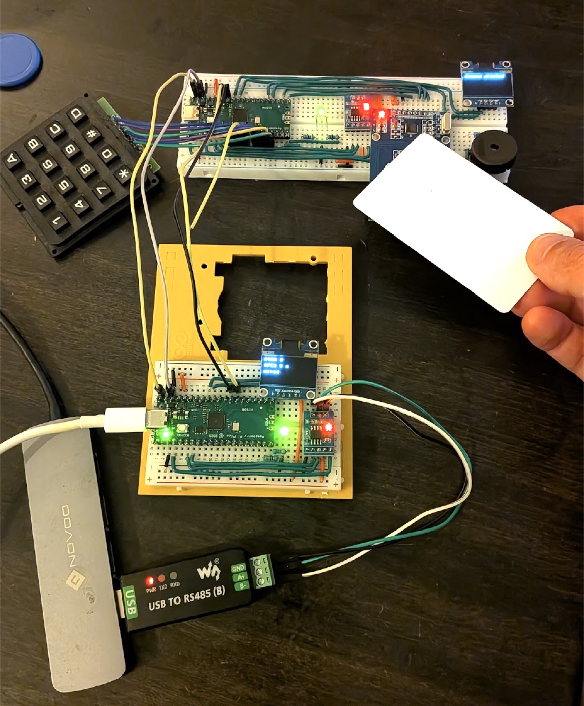
A hardware build log, written for a complete beginner, and the sequel to 19. A DIY reader. A second Raspberry Pi Pico plays a door on a half breadboard. It opens on the reader's wire or on an OSDP order from the controller, and it reports everything it does. Nothing here changes what a controller does.
A beginner's page
Same author, same rules as the reader: a beginner doing this for fun, not professional work. Every mistake along the way is listed at the end.
The reader only reports: a badge, a key. The door has a state: closed, open for a few seconds, or held open. The whole program turns around that state.
stateDiagram-v2
    direction LR
    state "Held open" as Held
    [*] --> Closed
    Closed --> Open: wire edge, or OUT pulse
    Open --> Open: another edge or pulse, 5 s again
    Open --> Closed: time is up, or OUT off
    Closed --> Held: OUT on
    Open --> Held: OUT on
    Held --> Closed: OUT off
A real door opens three ways. This one keeps two:
| By | Who decides | What the door knows |
|---|---|---|
| Two wires (dry contact) | the reader, on its own | "open", nothing else |
| OSDP, at address 2 | the controller | "open for 5 s", "stay open", "lock", plus a line of text |
| The exit button (left out here) | the door itself | "someone is leaving" |
The strike, the electric lock of a real door, is played by the Pico's own LED: lit means unlocked. A real relay would plug into the same logic later.
flowchart LR
    L["Reader, GP28"] -- "2 wires: signal + ground" --> P["Door Pico"]
    C["Controller (Mac)"] -- "RS-485 bus, address 2" --> P
    P --> G["Strike (the board's LED)"]
    P --> V["Red / green LED"]
    P --> E["Screen: state and countdown"]
How to read this page. It assumes the reader's page is done: soldering, laying a ribbon, reading a pin and speaking OSDP are not explained again. Each part ends with a test.
Contents
- What you need
- All the code
- Two Picos, one Mac
- The half breadboard
- Power, LED and strike
- The dry contact
- The screen
- Talking OSDP
- The power budget
- What comes next
- What went wrong, and the fix
- Glossary
What you need
Everything comes from the reader's shopping list (see 19. A DIY reader): most items came in packs.
| Part | Where from |
|---|---|
| A second Raspberry Pi Pico | the reader's list. The same USB-C RP2040 clone |
| A half breadboard, 400 points, 30 rows | an old Arduino starter kit |
| A second MAX3485 module | the reader's list, pack of 5 |
| A second 0.96" OLED screen | the reader's list |
| A bicolor LED and two 330 Ω resistors | the reader's packs |
| Solid wire and Dupont wires | the reader's packs |
| Three lever connectors (Wago type) | for the three-device bus |
The Waveshare USB to RS-485 adapter from the reader plays the controller again. A small USB hub helps: the door and the adapter both plug into the Mac.
All the code
On the door, saved under the same name: the reader's osdp.py and ssd1306.py. Then one program per part:
| Part | Program |
|---|---|
| 3 | 02-strike-and-led.py |
| 4 | 04-wired-input.py |
| 5 | 05-screen.py |
| 6 | 06-osdp-door.py |
On the Mac, next to the reader's controller.py and osdp.py:
| Program | What it does |
|---|---|
door_controller.py | Plays the controller for the reader (address 1) and the door (address 2). A known badge or PIN 1234 opens the door |
door_cycle.py | Talks to the door alone: held open, then locked, every 5 seconds. No reader needed |
1. Two Picos, one Mac
Prepare the Pico as in parts 1 and 2 of the reader: solder both header strips, then drag the MicroPython .uf2 onto the RPI-RP2 drive with BOOTSEL held.
From now on, two Picos share the Mac. Two rules:
- Thonny talks to one Pico at a time. Its interpreter menu, bottom right, lists one
usbmodemport per Pico. Plug the door alone the first time to learn which one it is. - Thonny stops the program of the board it connects to. The reader must therefore run on its own: save its program as
main.py, and keep Thonny on the door.
Label each Pico
Thonny cannot rename a port. Instead, connected to the door, type open("DOOR.txt", "w").close(). The empty file shows up in Thonny's Files pane the moment you connect, and tells you which board you are talking to.
Test: from machine import Pin; Pin(25, Pin.OUT).value(1) lights the LED on the board.
2. The half breadboard
The reader's layout needs 63 rows. The door lives on a 30-row half breadboard, and that changes three things.
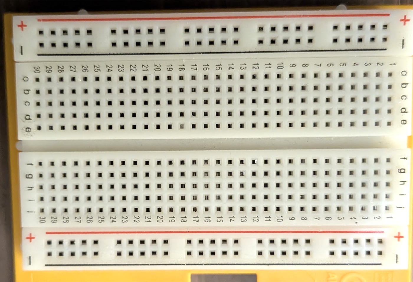
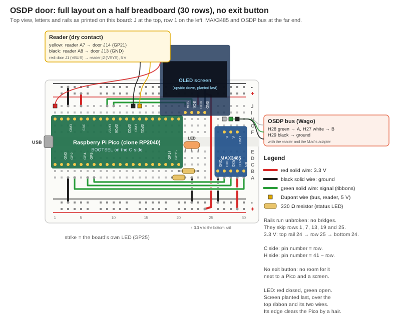
The letters run the other way. With row 1 on the left, J is at the top and A at the bottom: the reverse of the reader's board. The rails are reversed too: − outside at the top, + outside at the bottom. The plan below follows this board's own print.
The rails have gaps. Each rail has 25 holes in groups of five, and no hole faces rows 1, 7, 13, 19 and 25. A wire to a rail goes to the neighbouring hole. They run unbroken from end to end: no bridges.
The Pico takes rows 1 to 20, whole. Letting it hang off the end to save two rows does not work: the plastic runs about 1.7 holes past row 1, and pins 1, 2, 39 and 40 would rest on it. Cutting those pins was ruled out. On this board, the pin number is the row number on the C side (the BOOTSEL side), and 41 minus the row on the H side.
That leaves 10 rows for the LED, the MAX3485 and the screen. The screen alone is 27 mm wide and covers about 11 rows above the top rail, so the exit button had to go. The other choices follow from that:
- The MAX3485 sits at the far end, rows 26 to 30, shifted three columns towards the channel so its board clears the screen's.
- The screen is planted last, upside down, its board over the top rail and the wires laid under it. Its edge clears the Pico by a hair: dry-fit it before laying any wire.
- The resistors go straight from the Pico's pins to the LED's legs, with no green wire.
Final pin map
| Function | Pico pins |
|---|---|
| Bicolor LED | GP14 red, GP15 green |
| Strike | GP25, the board's own LED |
| Dry contact from the reader | GP21, pulled down |
| OLED (I2C1) | GP26 SDA, GP27 SCL |
| MAX3485 (UART1) | GP4 TX, GP5 RX, GP2 transmit enable |
| 5 V out to the reader | VBUS, pin 40 |
| Free | GP22, the exit button's pin, among others |
3. Power, LED and strike
Wiring (20 min)
| What | Holes |
|---|---|
| Pico | columns C and H, rows 1 to 20, USB on the left |
red, 3V3 | J5 → top rail + (inner line) |
black, GND | J3 → top rail − (outer line) |
black, GND | A3 → bottom rail − (inner line) |
| red, rail to rail | top rail +, row 24 → across row 25 → bottom rail +, row 24 |
| LED red, common, green | E21, E22, E23 |
| 330 Ω, red | A19 (GP14) → A21, standing up |
| 330 Ω, green | B20 (GP15) → B23 |
| black, common | A22 → bottom rail − |
Test: about 3.3 V between + and −, at the top and at the bottom.
The door opens on its own (10 min)
The first program has no input yet: the door opens for 5 seconds every 10 seconds. It introduces the heart of the project, the Door class:
class Door:
    """Closed, or open until a given time. The strike follows it."""

    def __init__(self):
        self.open_until = time.ticks_ms()

    def open_for(self, milliseconds):
        self.open_until = time.ticks_add(time.ticks_ms(), milliseconds)

    def is_open(self):
        return time.ticks_diff(self.open_until, time.ticks_ms()) > 0
Opening the door starts no timer: it writes down until when it stays open. Each turn of the loop, the strike and the LED follow is_open(). Nothing blocks, and the door closes by itself.
Test: 02-strike-and-led.py shows red at rest. Every 10 s, the LED turns green and the board's LED lights, for 5 s. If it is green at rest, turn the LED half a turn, middle leg in place.
4. The dry contact
The simplest door in the world: one wire that says "open". It is called a dry contact: no protocol, no address. The door knows neither who was accepted nor why. The reader decides, alone, as in part 10 of the reader.
The reader runs on its own (5 min)
Connect Thonny to the reader, open the reader's 10-door.py, then Save as… → Raspberry Pi Pico as main.py. Unplug and replug it: it shows "Enter PIN or show badge" without Thonny.
The wires (10 min)
| Wire | Reader | Door |
|---|---|---|
| yellow, signal | A7 (GP28) | J14 (GP21, pin 27) |
| black, ground | A8 | J13 (GND, pin 28) |
| red, 5 V | j2 (VSYS, pin 39) | J1 (VBUS, pin 40) |
The red wire is optional. It answers a practical problem: the Mac had no free port for a second Pico. The door, plugged in over USB, gets 5 V on its VBUS pin and passes it to the reader's VSYS, the Pico's power input. The reader's own regulator makes its 3.3 V from it. The black wire closes the loop: a current always needs a way back.
flowchart LR
    M["Mac USB port<br/>5 V"] -- "USB cable" --> DV["Door VBUS<br/>pin 40, J1"]
    DV --> DR["Door regulator<br/>5 V to 3.3 V"]
    DR --> D3["Door 3.3 V<br/>Pico, screen, LED, MAX3485"]
    DV -- "red wire, J1 to j2" --> RV["Reader VSYS<br/>pin 39, j2"]
    RV --> RR["Reader regulator<br/>5 V to 3.3 V"]
    RR --> R3["Reader 3.3 V<br/>Pico, RC522, screen, keypad, buzzer, MAX3485"]
    R3 -. "back to the door through the black wire, a8 to J13" .-> DV
Two rules with the 5 V wire
Check j2 twice: the reader's 3V3 is three holes further, and 5 V on a 3V3 or GP pin damages the board. And never plug the reader's own USB while the red wire is in: two 5 V sources on one Pico are best avoided. Remove the red wire first to reprogram the reader.
The code (10 min)
GP21 is pulled down: with the wire unplugged it reads 0, and the door stays closed. A loose wire must never open a door.
wired = wired_input.value() == 1
if wired and not was_wired:
    door.open_for(OPEN_MS)
was_wired = wired
The door reacts to the edge, the moment the signal goes to 1, not for as long as it stays there. The reader sends a pulse of about 1.5 s, and the door keeps its own 5 s: the door decides how long, the wire only says when.
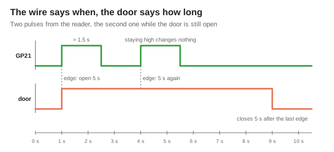
Test: with 04-wired-input.py running, 1234# on the reader turns it green and opens the door for 5 s. A wrong code leaves it closed.
No reader at hand
A short wire from the top rail +, touched against J14 for a second, plays the reader: it is the same 3.3 V. A meter in voltage mode does not work, it only listens.
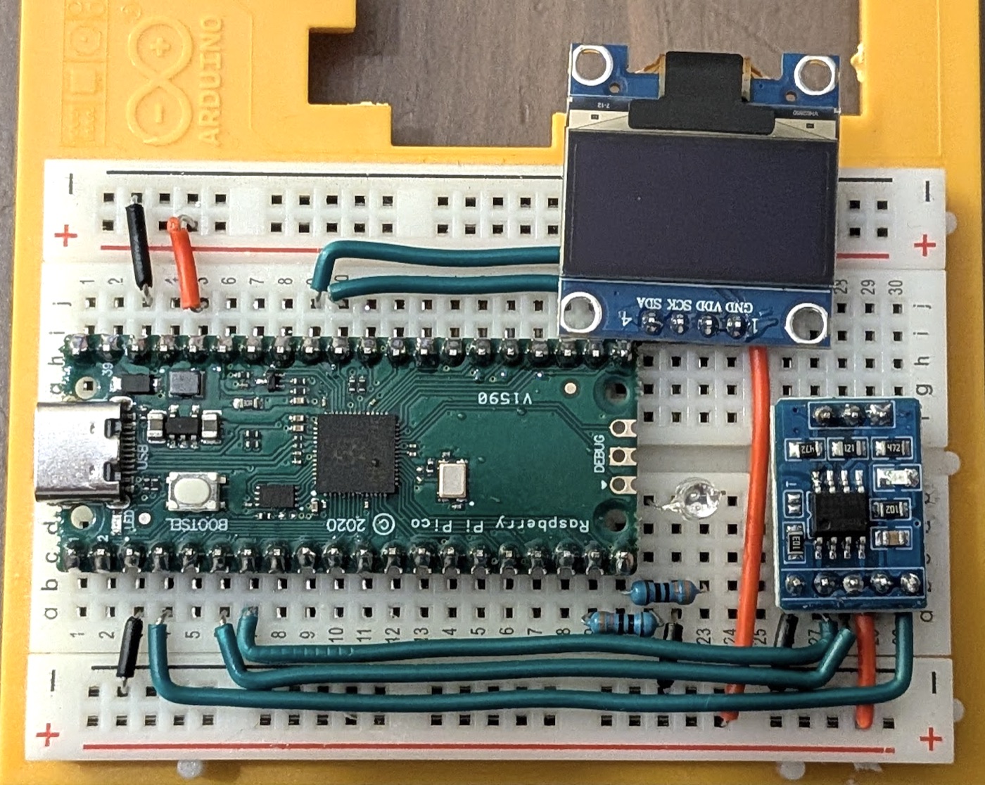
5. The screen
Wiring (15 min)
Lay the wires first: the screen covers them.
| What | Holes |
|---|---|
green, GP26 → SDA | J10 → J21, top ribbon, closest track |
green, GP27 → SCK | J9 → J22, over it |
| red | J23 → top rail + |
| black | J24 → top rail − |
| screen, upside down, its board over the rail | I21 to I24 (SDA, SCK, VDD, GND) |
Test: from machine import I2C, Pin; I2C(1, sda=Pin(26), scl=Pin(27)).scan() returns [60].
The program (5 min)
Save the reader's ssd1306.py on the door first: without it, the program stops on ImportError.
The screen shows DOOR, the state (CLOSED or OPEN 4 s) and why it opened (wired). It redraws only when something changes, and at most every 200 ms: drawing takes time, and the loop must stay free.
Test: 05-screen.py shows CLOSED. 1234# on the reader shows OPEN 5 s, OPEN 4 s… then CLOSED, with wired below.
6. Talking OSDP
The door becomes a second OSDP device, at address 2, on the same bus as the reader. The controller asks each in turn. A badge read by the reader opens the door: the architecture of a real site, and of the lab suitcase.
The MAX3485 (20 min)
| What | Holes |
|---|---|
GND, TXD, RXD, VCC, EN | B26 to B30 |
B, A, GND | F27 to F29 |
| black | A26 → bottom rail − |
| red | A29 → bottom rail + |
GP5 ← TXD | A7 → A27, bottom ribbon, closest track |
GP4 → RXD | A6 → A28 |
GP2 → EN | A4 → A30, outermost track |
Test: the module's red LED lights.
The bus with three devices (15 min)
RS-485 is a bus: every device hangs on the same three wires, A to A, B to B, ground to ground. Each has its own address, and only the one addressed answers. One lever connector per wire, three wires in each:
flowchart LR
    C["Controller<br/>Mac and USB adapter<br/>the only one to speak first"] === W["3 lever connectors<br/>A, B, ground"]
    W === R["Reader<br/>address 1"]
W === D["Door<br/>address 2"]| Connector | Adapter | Reader | Door |
|---|---|---|---|
green, A | A+ | A34 | H28 |
white, B | B- | A33 | H27 |
| black, ground | GND | A35 | H29 |
Each MAX3485 carries a 120 Ω termination resistor, and the adapter may too. Three in parallel make 40 Ω, below what the standard expects. Over a metre of wire it works. If frames start to go missing, that is the first suspect.
The programs (15 min)
The reader's osdp.py now knows OUT, ISTAT and OSTAT.
- On the door: save
osdp.pyandssd1306.py, then run06-osdp-door.pyfrom Thonny. - On the reader: save the new
osdp.py, and12-4-controller-decides.pyasmain.py. - On the Mac:
cd docs/assets/diy-door/code
python3 door_controller.py
Test: at startup, ID and CAP answer for reader and for door. The door announces 1 input (the wire), 1 output (the strike), 1 LED and 1 screen.
What the controller does (20 min)
| On the reader | Sent to the door | The door |
|---|---|---|
badge 1, or 1234# | OUT 5 s + TEXT | open 5 s, then closes by itself |
7777# | OUT on for good | HELD OPEN, until told otherwise |
0000# | OUT off for good | closed, and a running opening stops |
| another badge, another code | nothing | closed |
sequenceDiagram
    participant R as Reader (address 1)
    participant C as Controller (Mac)
    participant D as Door (address 2)
    C->>R: POLL
    R-->>C: RAW: badge 6B AD 30 8E
    C->>R: LED green, BUZ, TEXT "Access granted"
    R-->>C: ACK, one per command
    C->>D: OUT: output 0, pulse, 50 tenths of a second
    D-->>C: ACK
    C->>D: TEXT "badge: open 5 s"
    D-->>C: ACK
    C->>D: POLL
    D-->>C: OSTATR: strike open
The opening time travels inside the command: OUT has an "on for X, then back to rest" mode. The standard counts X in tenths of a second, so 5 s is written 50.
The screen splits the work. The first three lines are the door's own: its name, its state and the reason it opened. Only the last line comes from the controller, through TEXT. The controller gives orders, the door decides what they look like.
The door reports what it did alone
An OSDP device never speaks first. About every 0.2 s, the controller sends POLL, "anything new?", and the door answers ACK, "nothing". Those quiet answers are not printed.
When the wire opens the door without asking anyone, two things change, and the door tells the next POLLs:
sequenceDiagram
    participant W as Reader's wire
    participant D as Door (address 2)
    participant C as Controller (Mac)
    C->>D: POLL
    D-->>C: ACK, nothing new
    W->>D: 3.3 V edge on GP21
    Note over D: opens on its own, for 5 s
    C->>D: POLL
    D-->>C: ISTATR: wire on
    C->>D: POLL
    D-->>C: OSTATR: strike open
    W->>D: back to 0 V, 1.5 s later
    C->>D: POLL
    D-->>C: ISTATR: wire off
    Note over D: 5 s are up, closes
    C->>D: POLL
    D-->>C: OSTATR: strike closed
door <- ISTATR ...
door input: wired pulse on
door <- OSTATR ...
door is now open
ISTATR is the state of its inputs, OSTATR the state of its outputs. Without them, the controller would never know that a door opened by another path than itself. In wardn, that is what feeds the activity log.
Test: a badge opens the door over OSDP. Touch J14 with the wire from the rail: the Mac prints wired pulse on, then door is now open, then closed 5 s later.
Without the reader: the door on a cycle (5 min)
door_cycle.py plays a controller that only talks to the door. Every 5 s it alternates OUT on (held open) and OUT off (locked), and prints what the door reports. The adapter wired straight to H27 to H29 is enough. Without the reader, door_controller.py also works, but fills the terminal with reader <- no reply.
Test: the screen alternates HELD OPEN and CLOSED, the LED green and red. Touching J14 during a locked phase still opens the door for 5 s: the controller was not asked, but it finds out.
What the door understands
| Command | Code | The door… | Reply |
|---|---|---|---|
POLL | 0x60 | says "nothing new", or reports an input or output change | ACK, ISTATR, OSTATR |
ID, CAP | 0x61, 0x62 | introduces itself: 1 input, 1 output, 1 LED, 1 screen | PDID, PDCAP |
OUT | 0x68 | opens for a while (code 5), holds open (2) or locks (1) | ACK |
ISTAT | 0x65 | gives the state of the reader's wire | ISTATR |
OSTAT | 0x66 | says whether the strike is open | OSTATR |
LED | 0x69 | forces a colour for a while, then back to red or green | ACK |
TEXT | 0x6B | writes a line at the bottom of the screen | ACK |
Building the door corrected the real controller: wardn-osdp sent OUT with code 3 and a time in milliseconds, and BUZ with tone 1, which means "silence". Both were checked against libosdp, the reference open implementation.
7. The power budget
Both Picos run from one USB port of the Mac. Why that is fine, in numbers. These are estimates from typical datasheet values, except the one measured line.
flowchart LR
    M["Mac USB port<br/>at least 500 mA"] -- "about 85 mA in all" --> D["Door<br/>about 40 mA, estimated"]
    D -- "red wire<br/>42 to 43 mA, measured" --> R["Reader"]
What each board draws on its 3.3 V. Each Pico makes its own 3.3 V, and everything on 3V3 goes through its regulator.
| Door | Current |
|---|---|
| Pico, MicroPython running | about 25 mA |
| Board LED (the strike), lit | about 2 mA |
| Bicolor LED, one colour: (3.3 − 2.0) V / 330 Ω | about 4 mA |
| OLED screen, depending on lit pixels | 10 to 20 mA |
| MAX3485 at rest, with its LED | about 2 mA |
| At rest | about 50 mA |
| MAX3485 answering, for a few milliseconds | + about 40 mA |
| Reader | Current |
|---|---|
| Pico | about 25 mA |
| RC522, antenna on, with its LED | about 25 mA |
| OLED screen | 10 to 20 mA |
| Bicolor LED | about 4 mA |
| Piezo buzzer, keypad | under 3 mA |
| MAX3485 at rest, with its LED | about 2 mA |
| At rest | about 80 mA |
| MAX3485 answering | + about 40 mA |
The 40 mA peak: the MAX3485 pushes about 1.5 V into the termination resistors, three 120 Ω in parallel, so 40 Ω. 1.5 V / 40 Ω ≈ 40 mA.
On the 5 V side. A regulator converts power, not current. It takes 5 V and gives 3.3 V with about 85 % efficiency (the official Pico's figure, not checked on the clone):
current at 5 V ≈ current at 3.3 V × 3.3 / (5 × 0.85) ≈ current at 3.3 V × 0.78
| At rest | During an OSDP reply | |
|---|---|---|
| Door (estimated) | about 40 mA | about 70 mA |
| Reader, through the red wire | about 60 mA estimated, 42 to 43 mA measured | about 95 mA |
| Both, on the door's USB | about 85 mA with the measurement | about 130 mA |
The peaks do not add up: on an RS-485 bus, only one device talks at a time.
Why it works:
- A USB port must supply at least 500 mA (USB 2) or 900 mA (USB 3). 130 mA is about a quarter of 500.
- Each Pico's 3.3 V regulator handles about 300 mA. The door draws at most 90, the reader at most 120.
- The red wire carries only the reader's current, under 100 mA: any Dupont wire handles it.
Measure it (5 min). The meter takes the red wire's place, in series, so the reader's current flows through it:
Door J1 (5 V) ──► red probe ─[meter]─ black probe ──► Reader j2 (VSYS)
On the ANENG SZ304: selector on 200m in the A zone, SEL until DC, red lead in the BAT/mA socket, black in COM. Red probe in J1, black in j2, door on USB, reader's USB unplugged. Afterwards, put the red lead back in VΩHz at once: left in BAT/mA, the next voltage measurement is a short circuit and blows the fuse.
This only measures the reader: the door's own current enters through its USB cable and never crosses the meter. The total would need a USB tester between the Mac and the cable.
8. What comes next
- The exit button. Leaving must always work, even when the controller is down: a real door decides that on its own. It comes back on two wires, between
GP22(pin 29,H12) and ground. - A real strike. A relay or a transistor on a free pin, in place of
GP25. Only the pin number changes in the code. - One port for both links. The bus's
A,Band ground holes could take either the OSDP bus or the reader's two wires, the door picking the mode in its program. It needs a 10 kΩ resistor between lineAandGP21: the adapter's transceiver runs on 5 V, more than a Pico pin accepts. - 12 V power. A real site runs one 12 V supply along the bus, a fourth wire next to
A,Band ground. Each box makes its own 5 V with a small converter intoVSYS, set with a meter before it is plugged in.
What went wrong, and the fix
| Symptom | Cause | Fix |
|---|---|---|
| The reader's layout does not fit | A 30-row half breadboard, not a 63-row MB-102 | A new plan: MAX3485 at the far end, screen planted last, no exit button |
| The Pico cannot hang its pins off the end | The plastic runs 1.7 holes past row 1 | Keep the Pico whole on rows 1 to 20, and drop the button |
| A rail wire has no hole to go to | Rails skip rows 1, 7, 13, 19 and 25 | Use the neighbouring hole |
| Every hole on the plan is mirrored | This board letters its columns the other way | Redraw the plan with the board's own letters and rails |
| The programs still read an exit button | The button was dropped after they were written | Remove it from every program, and CAP now announces 1 input |
| No reader at hand to test the wire | A wire from the + rail touched against J14 | |
05-screen.py stops on ImportError | ssd1306.py is not on the door | Save it on the door first |
| Two Picos, no free USB port | The door's VBUS feeds the reader's VSYS, with a shared ground | |
The terminal fills with reader <- no reply | The reader is absent, and quiet POLLs are not printed | Normal. Use door_cycle.py to test the door alone |
| The OSDP test showed nothing new on the door | The news is on the Mac side | ISTATR and OSTATR tell the controller what the door did alone |
| The current measurement stayed at 0 | 200m exists in volts and in amps, AC was selected, the lead was in the wrong socket | A zone, DC, red lead in BAT/mA. A voltage check (5.23 V on J1) first proved the probes were fine |
| "Both devices" turned out to be one measurement | The meter replaced only the reader's 5 V wire | Measure the total with a USB tester, or keep the door's estimate |
Glossary
| Word | Meaning |
|---|---|
| Strike | The electric lock of a door. Here, the Pico's own LED |
| Dry contact | A wire that only says "open": no protocol, no address |
| Edge | The moment a signal changes, as opposed to its level |
| Pull-down | An internal resistor that holds an input at 0 when nothing drives it |
VBUS | Pin 40: the 5 V that arrives over USB |
VSYS | Pin 39: the Pico's power input, turned into 3.3 V by its regulator |
| In series | In the current's path, as a meter must be to measure a current |
| Termination | The 120 Ω resistor between A and B at the ends of an RS-485 bus |
ISTATR, OSTATR | OSDP replies with the state of a device's inputs, and of its outputs |
OUT | The OSDP command that drives an output: pulse, on or off |
The door opens on the reader's wire or on the controller's order, shows its state and countdown, and reports every change it makes on its own, from a single USB port.