21. A DIY power supply
A hardware build log, written for a complete beginner, and the third part after 19. A DIY reader and 20. A DIY door. One mains plug feeds the whole bench: a 12 V supply, three converters that each make 5 V, the Raspberry Pi on one of them, the reader and the door on another. It is the power part of 16. The lab suitcase. Nothing here changes what a controller does.
A beginner's page
Same author, same rules as the reader and the door: a beginner doing this for fun, not professional work. Every mistake along the way is listed at the end.
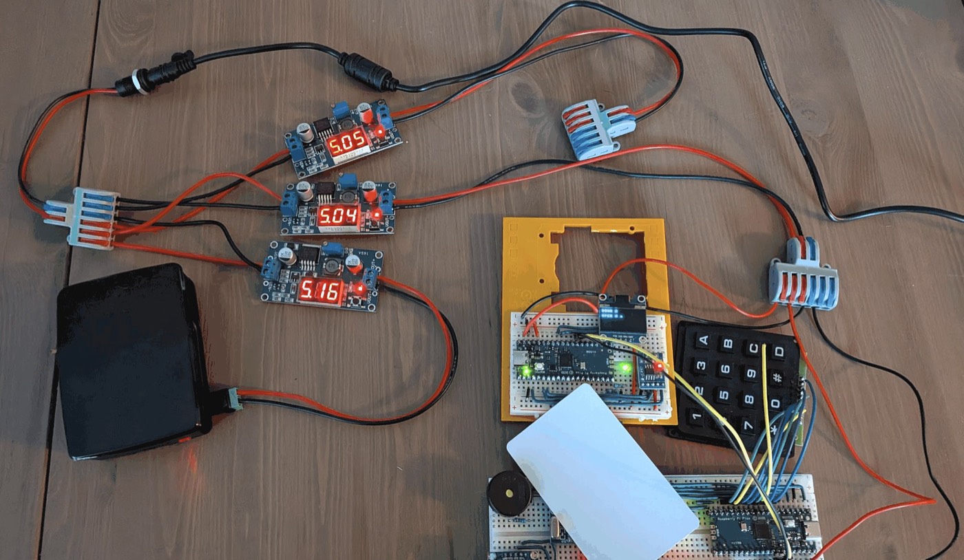
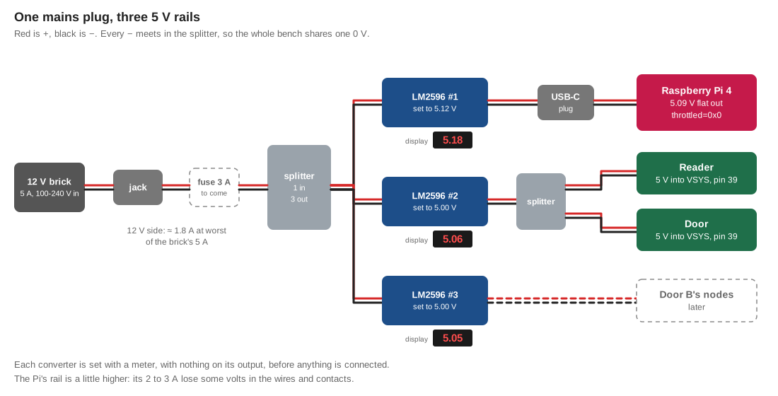
Until now, every Pico ran from a USB cable, and the Mac was the power supply. A suitcase cannot carry a Mac. Here, a single 12 V brick feeds three small converters, and each one makes 5 V for part of the bench:
| Converter | Feeds | Set to |
|---|---|---|
| LM2596 #1 | the Raspberry Pi, through a USB-C plug | 5.12 V |
| LM2596 #2 | door A's nodes: the reader and the door | 5.00 V |
| LM2596 #3 | door B's nodes, later | 5.00 V |
How to read this page. It assumes the reader's and the door's pages are done: using a meter and moving a wire on a breadboard are not explained again. No soldering in this part: every joint is a screw or a lever. Each part ends with a test.
Contents
- What you need
- Why 12 V, and why 5 V
- The brick
- The jack and the splitter
- Setting the converters
- The Raspberry Pi on #1
- The reader and the door on #2
- The power budget
- What comes next
- What went wrong, and the fix
- Glossary
What you need
| Part | Notes |
|---|---|
| A 12 V 5 A mains brick, 5.5 x 2.1 mm plug | Read its label: it must say 100-240V |
| A plug adapter, if the brick came with a foreign plug | Rated 250 V, marked CE, no play once plugged in |
| A 5.5 x 2.1 mm female panel jack | Ours came with red and black wires already soldered |
| Three LM2596 modules, with a voltmeter and screw terminals | The version with a display costs a little more and saves a lot of guessing |
| Two lever splitters, one input and three outputs per colour | Red for +, blue for − |
| A USB-C male plug with screw terminals | For the Raspberry Pi |
| Red and black 18 AWG wire | For everything between the brick and the converters, and the Pi's cable |
| Red and black 22 AWG solid wire | From the second splitter to each breadboard |
| A multimeter and a small flat screwdriver | |
| Masking tape and a pen | To label each converter |
Still to come, in the shopping basket: a 3 A inline fuse and a USB tester. Both are covered in What comes next.
Why 12 V, and why 5 V
A converter makes 5 V from 12 V without burning the difference. A simple regulator turns the extra 7 V into heat. The LM2596 is a buck converter: it switches the current on and off tens of thousands of times a second, and its big coil smooths the result. It wastes about 15 %, where a simple regulator would waste 60 %.
It converts power, not current. The Pi can draw up to 3 A at 5 V. On the 12 V side, that is only about 1.5 A:
current at 12 V ≈ current at 5 V × 5 / (12 × 0.85) ≈ current at 5 V × 0.5
Why the nodes get 5 V, not 3.3 V. Everything on a node runs on 3.3 V, but each Pico makes its own 3.3 V from whatever reaches its VSYS pin. Sending 5 V there, rather than 3.3 V straight to the components, keeps three good properties:
- Some voltage lost in the wires costs nothing.
VSYSaccepts 1.8 to 5.5 V. A 5 V rail that sags to 4.7 V still gives a clean 3.3 V. A 3.3 V rail that sags to 3.0 V is already outside what the RC522 and the MAX3485 accept. - No two regulators fight. 3.3 V sent to a Pico's
3V3pin meets the Pico's own regulator on the same wire, unless3V3_ENis tied to ground on every board. - A fault stays on its node. A short on one reader's 3.3 V only stops that reader.
It also changes nothing: on USB, the Picos already received 5 V. The converter simply replaces the cable.
1. The brick
Read the label (1 min)
Ours arrived with a US plug. The label decides everything:
INPUT AC 100-240V 50/60Hz: it accepts European 230 V, and only the plug's shape is wrong. A plug adapter does the job.120Valone: do not use it in Europe, adapter or not.
Ours, a JX-12050, said 100-240V. The adapter is rated 250 V and 6 A, far above the brick's 60 W.
Check the plug's polarity (5 min)
The round plug has a hole in the middle, usually the +, and an outer sleeve, usually the −. "Usually" is not enough.
- [x] Meter on
20V,DCon the screen, red lead in theVΩHzsocket. Brick on the mains, its plug in the air. - [x] Red probe in the centre hole, black probe on the sleeve: a value around 12, positive. A minus sign means the centre is
−: stop.
2. The jack and the splitter
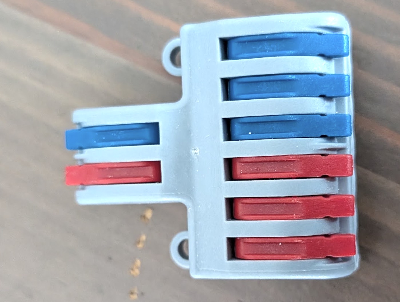
The splitter is made for this: one input and three outputs for the + (red levers), the same for the − (blue levers). Each side is one piece of metal inside.
Check, then wire (15 min)
- [x] The jack's wires. Continuity
·))): the red wire beeps with the pin in the middle of the jack, the black wire with the metal wall around it. The seller's colours are not a promise. - [x] The splitter. Continuity, levers up, one probe in each hole: the red input beeps with all three red outputs, the blue input with all three blue ones. Red and blue never beep together.
- [x] Jack's red wire in the red input, black wire in the blue input.
A wire goes in with the lever up: strip 10 to 11 mm, push it to the end, lower the lever, pull gently.
The test (2 min)
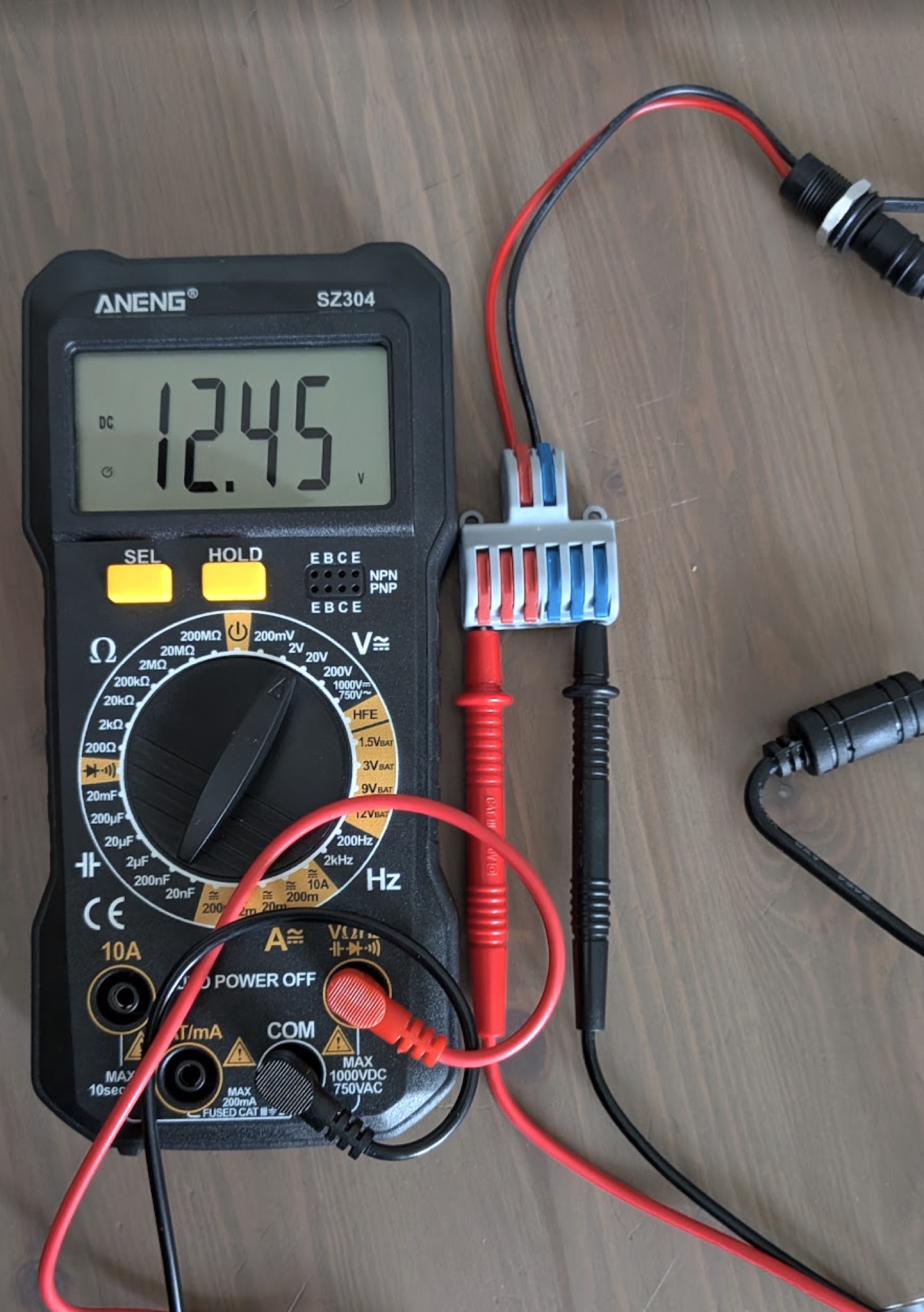
- [x] Brick on. Meter on a red and a blue output of the splitter: 12.45 V, positive.
One reading checks three things at once: the brick's plug, the jack's wires and the splitter all point the right way. 12.45 V with nothing drawing current is normal for a 12 V brick.
3. Setting the converters
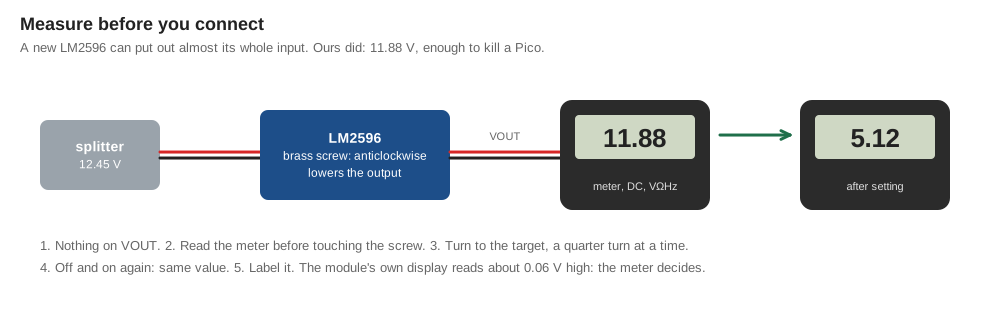
The rule of this part: nothing is ever connected to a converter's output before that output has been measured. A new LM2596 can put out almost its full input. Ours did.
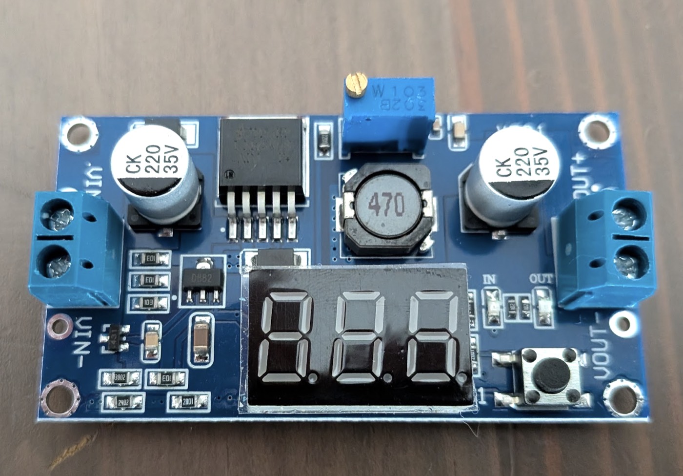
The module, as it comes:
VIN+andVIN−on one side,VOUT+andVOUT−on the other, all screw terminals.- The potentiometer: the blue cube marked
103, with a brass screw. It is a multi-turn one: 10 to 20 turns can pass before the voltage moves. - The display, and a button next to it: the button switches between the input voltage (LED
INlit) and the output voltage (LEDOUTlit).
#1, for the Pi (20 min)
- [x] Brick off. 15 cm of red and black 18 AWG:
VIN+andVIN−on the module, a red and a blue output on the splitter. - [x] Nothing on
VOUT. Brick on. - [x] Meter on
VOUT+andVOUT−before turning anything. Ours read 11.88 V. A Pico plugged in as delivered would have died. - [x] Turn the brass screw anticlockwise: the voltage goes down. If yours goes up, turn the other way. Near 5 V, a quarter turn at a time.
- [x] Stop at 5.12 V on the meter. Brick off, on again: still 5.12.
- [x] Label it on masking tape: "#1 — Pi — 5.12 V".
#2 and #3, for the nodes (20 min)
- [x] The same, each on its own pair of splitter outputs, brick off before every new wire. Set both to 5.00 V on the meter.
- [x] Label them: "#2 — door A", "#3 — door B".
- [x] All three on, after 5 minutes: cold to the touch. A module that warms up with nothing on its output is faulty.
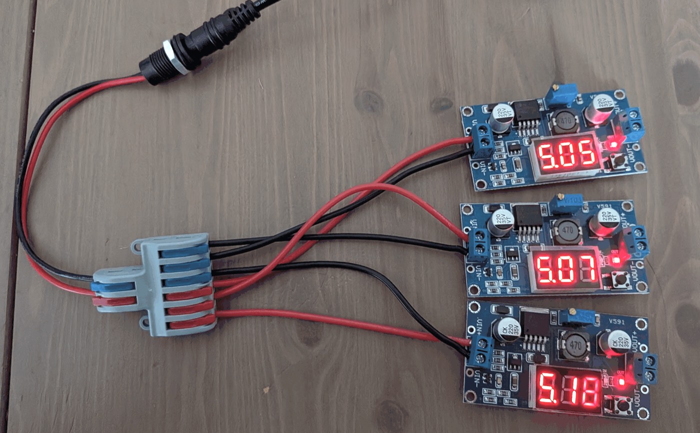
The meter decides, not the display
The module's display is handy to watch, not to set:
| Meter | Display | Gap |
|---|---|---|
| 12.45 V (input) | 12.5 V | +0.05 |
| 11.9 V (output, before setting) | 12.0 V | +0.1 |
| 4.94 V | 5.00 V | +0.06 |
| 5.00 V (#2) | 5.06 V | +0.06 |
| 5.12 V (#1) | 5.18 V | +0.06 |
The gap moved between 0.04 and 0.07 V while we turned the screw. Two readings could even look backwards, 5.04 on the display for 4.99 on the meter, then 5.05 for 4.98. Both instruments round to the hundredth and hesitate between two values: under 0.03 V, a difference means nothing. Set with the meter, ±0.02 V. Use the display afterwards to spot a rail that drifted.
Each module needs its own screw position for the same 5 V. That is normal. The chip holds its output where a divider made of a fixed resistor and the potentiometer gives it 1.23 V. Its own reference, the resistor and the potentiometer all vary by a few percent from one module to the next, and the screw starts wherever the factory left it.
4. The Raspberry Pi on #1
Why 5.12 V, not 5.00 V (2 min of reading)
A Pico draws about 60 mA. A Raspberry Pi 4 can draw 2 to 3 A, and volts get lost on the way: a little in the wires, a little in each screw and contact, and the converter sags a little under load. Under 4.63 V, the Pi flags an undervoltage and slows down. Starting from 5.12 V keeps a margin. The official Pi supply puts out 5.1 V for the same reason, and USB tolerates up to 5.25 V.
The USB-C plug (10 min)
The plug has two screw terminals, marked + and −.
- [x] Brick off. Red 18 AWG from
VOUT+of #1 to+, black fromVOUT−to−. - [x] Check the polarity without the Pi. A probe cannot reach inside a USB-C plug, but its metal shell is ground on almost every plug. Continuity between the
−screw and the shell: beep. Between the+screw and the shell: silence.
A Pico first (10 min)
A spare Pico costs a few euros, the Pi much more. The Pico tests the plug first.
- [x] On the Mac, save the reader's first program,
01-blink.py, asmain.pyon a bare Pico. - [x] Brick off. The USB-C plug into the Pico. Brick on: the LED blinks.
- [x] Meter between pin 36 (
3V3) and pin 38 (GND): 3.33 V.
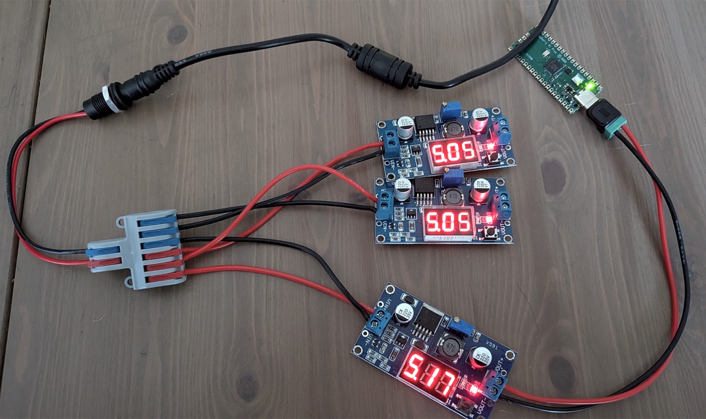
The whole chain works, end to end: brick, jack, splitter, #1, plug, Pico.
The Pi under load (15 min)
- [x] Brick off, Pi in place of the Pico. Brick on: the Pi boots.
- [x] On the Pi:
vcgencmd get_throttled
throttled=0x0 means the Pi has never been short of voltage since it started. Ours said 0x0 after booting, one of the moments it draws the most.
- [x] All four cores flat out, without installing anything:
for i in 1 2 3 4; do yes > /dev/null & done
pgrep -c yes
The prompt comes back at once: the & runs each yes in the background. pgrep counts them: 4.
- [x] Meter on
VOUTof #1 during the load: 5.09 V, against 5.12 V at rest. The converter gives up only 0.03 V. - [x] After 10 minutes,
vcgencmd get_throttledagain: still0x0. Then stop the load:
killall yes
- [x] #1 is slightly warm. Hot enough that you cannot leave a finger on it would mean stop.
5. The reader and the door on #2
Where the 5 V goes
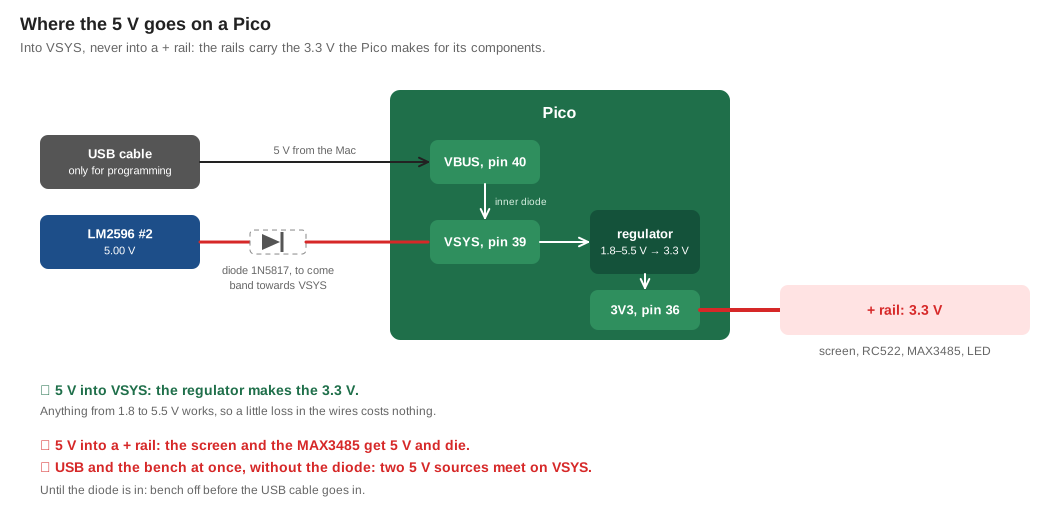
Into VSYS, pin 39, never into a + rail. The rails of both breadboards carry 3.3 V: 5 V there would destroy the screens and the MAX3485 modules.
| Board | VSYS | Ground |
|---|---|---|
| Door (page 20) | J2 | the top − rail |
| Reader (page 19) | row 2 on the A side, where page 20's red wire went (j2 there) | the top − rail, next to A3 |
Wiring (15 min)
A second splitter, its input on VOUT of #2, gives one pair of outputs per node.
- [x] Brick off. Every USB cable off the reader and the door.
- [x] Door: red 22 AWG solid wire from a red output to
J2, black from a blue output to the top−rail. - [x] Reader: the same, to row 2 and its top
−rail. - [x] The dry contact stays: yellow from the reader's
A7(GP28) and black fromA8to the door, as on page 20. - [x] Brick on. Meter: about 5.0 V between
VSYSand−, about 3.3 V between each board's+and−rails. - [x] A known badge on the reader: green, beep, and the door shows
OPEN 4 s.
Solid wire holds better in a lever than a Dupont pin: the pin is short and square, and the lever grips it poorly.
The reader used to take its 5 V from the door. On page 20, the door's VBUS (pin 40, J1) fed the reader's VSYS. VBUS only carries the USB cable's 5 V. With the door on VSYS and no USB, VBUS is dead, and the reader would go dark. Each node now has its own pair of wires.
The rule, until a diode is in
Bench on, no USB cable on any Pico. Without a diode, the Mac's 5 V and the converter's 5 V would meet head-on on VSYS. To change a program: brick off first, USB in second.
The fix is a Schottky diode (1N5817) on each node's red wire, its band towards VSYS. Current then only flows from the bench into the Pico, and the USB cable can go in at any time. The diode costs about 0.3 V: 4.7 V on VSYS, plenty.
6. The power budget
Measured where we could, estimated elsewhere.
| Rail | What it carries | Measured |
|---|---|---|
| 12 V input | everything | 12.45 V at rest |
| #1 | Raspberry Pi 4, four cores flat out | 5.12 V at rest, 5.09 V under load, throttled=0x0 after 10 min |
| #2 | reader and door | 5.05 V on the display at rest, 5.04 V with both nodes running |
| #3 | nothing yet | 5.05 V on the display |
The current on the 12 V side, at worst:
| Load | At 5 V | At 12 V |
|---|---|---|
| Raspberry Pi 4, flat out | up to 3 A | ≈ 1.5 A |
| Five Pico nodes with screens and readers | ≈ 0.5 A | ≈ 0.25 A |
| Total | ≈ 1.8 A, of the brick's 5 A |
The reader alone was measured at 42 to 43 mA on page 20. The Pi's real current waits for the USB tester.
7. What comes next
- A 3 A fuse on the red wire, right after the jack, before the splitter. It protects the wires, not the electronics: it melts before a short heats a wire enough to melt its insulation in a closed case. 2 A would be too tight: the three converters' capacitors charge all at once at power-on. Until it is in, the bench never runs unattended.
- A USB tester between the plug and the Pi, to read the voltage that actually reaches the Pi, and its current.
- The diodes, one per node, and the USB rule goes away.
- A drop of nail varnish on each brass screw once the settings are final: transport can turn a potentiometer.
- On a soldered board, the power arrives on a keyed two-pin JST-XH connector, which cannot go in backwards. On the reader's perfboard,
VSYSandGNDare side by side at the top left of the Pico.
What went wrong, and the fix
| Symptom | Cause | Fix |
|---|---|---|
| The brick has a US plug | Wrong plug option on the order | The label says 100-240V: a CE plug adapter rated 250 V |
The meter reads 00.11 on 12 V | The screen showed AC | SEL until DC |
Then the meter reads 00.00 | The red lead was in the BAT/mA socket | Red lead in VΩHz. Check the mode and the socket before every reading |
| #1 put out 11.88 V as delivered | The factory leaves the screw anywhere | Measure every output before connecting anything |
| Two readings, 12.45 and 11.88 V, looked contradictory | One was the converter's input, the other its output | Always note where the probes were |
| The display and the meter disagree by 0.04 to 0.07 V | The display is not calibrated, and both round to the hundredth | Set with the meter, watch with the display |
| Each module needed a different screw position for 5 V | Part tolerances, and a random starting point | Normal: set each one on the same meter |
| The Pi's module got mixed up with the others | No labels | Label each converter as soon as it is set |
for … yes … & returns at once | & runs each yes in the background | pgrep -c yes shows they run |
The reader would go dark with the door on VSYS | It took its 5 V from the door's VBUS, which only USB feeds | One pair of wires per node from the splitter |
| A Dupont pin does not hold in a lever | Too short and square | 22 AWG solid wire, stripped 11 mm |
Glossary
| Word | Meaning |
|---|---|
| Buck converter | A converter that lowers a voltage by switching it fast and smoothing it with a coil, with little loss |
| Multi-turn potentiometer | An adjustable resistor whose screw turns many times end to end, for fine settings |
| At rest, under load | With nothing drawing current, and with the real consumer running |
| Sag | The small drop of a supply's voltage when current is drawn |
VSYS | Pin 39: the Pico's power input, from 1.8 to 5.5 V, turned into 3.3 V on the board |
VBUS | Pin 40: the 5 V of the USB cable, and nothing else |
| Schottky diode | A diode with a small voltage drop, about 0.3 V, that lets current through one way only |
| Fuse | A thin wire that melts and cuts the circuit when too much current flows |
| Lever splitter | A connector where one input feeds several outputs, each wire held by a lever |
throttled | The Pi's record of undervoltage and overheating since it started. 0x0 means none |
One mains plug feeds the Raspberry Pi, the reader and the door. Each converter was set with a meter before anything touched it, and the Pi never ran short of voltage, even flat out.